Written By: Dean Shali
Fact Checked By: Sabré Cook
Reviewed By: Tamara Warren
Most of the time “No-Start Problems” often begins with some kind of electrical flow, not the engine itself.
Because, now-a-days every modern vehicle actually depends on a small but really important electrical component known as “IGNITION SWITCH”, which quietly controls the flow of the power to almost every major system in your car.
Also, when you turn the key or press the start button, then the ignition switch is actually responsible for waking up the battery circuit, powers the dashboard, activates the fuel system and finally sends the signal to crank the engine as well.
Plus, in many no-start situations: the driver often suspects the battery or starter first, but there’s even studies in automotive diagnostics that shows that ignition switch faults are really common hidden cause of intermittent electrical failures, specially in the older or high-mileage vehicles as well.
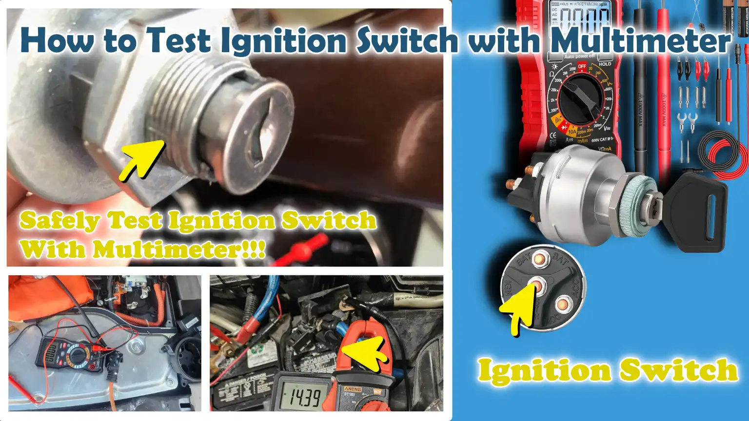
That’s why, in this guide you’ll learn How to Test Ignition Switch with Multimeter, so that you can use simple digital multimeter and measure voltage flow through the each ignition position, so that you can confirm whether the switch is delivering correct electrical signals or actually breaking down internally.
Now, Understand About the Ignition Switch System
1. The Basic Function of the Ignition Switch at Different Key Positions – OFF, ACC, ON, START
The ignition switch controls the flow of electricity within your vehicle based on the position of the key.
In the OFF position, power to all main circuits is cut off to prevent the battery from discharging.
In the ACC (Accessory) position, power is supplied only to accessories such as the radio or power windows.
In the ON position, the switch supplies power to the engine control system, fuel pump relay, sensors and dashboard instruments, thereby preparing the vehicle for ignition.
In the START position, it sends power to the starter relay or solenoid to crank the engine.
Each position plays a specific role in safely starting and operating the vehicle.
2. How Does It Supply Power to the Electrical System and Starter Relay?
Inside the ignition switch, there are metal contacts that open and close electrical circuits as the key is turned.
These contacts route the battery voltage to various systems according to the position of the key.
In the ON mode, power is directed to the engine’s electronics and control modules.
In the START mode, power is momentarily sent to the starter relay, which activates the starter motor to crank the engine.
As soon as the engine starts, the switch automatically returns to the ON position, allowing the engine to continue running while the starter disengages.
3. What Is the Difference Between the Ignition Switch and the Ignition Cylinder?
The ignition cylinder is the mechanical component into which you insert and turn the key.
It primarily controls the physical movement of the key and, in some vehicles, also governs the operation of the steering lock system.
The ignition switch is the electrical component that effectively distributes power to the vehicle’s various systems.
Rotating the internal mechanism within the cylinder activates the ignition switch, thereby controlling the electrical output.
In vehicles equipped with a push-start system, an electronic button may take the place of the cylinder; however, the function of the ignition switch remains present behind that system.
Tools
| Tools | Why It Is Needed | How to Use It in Ignition Switch Testing |
|---|---|---|
| Digital Multimeter – DMM | This is the primary tool for checking voltage and verifying whether the ignition switch is transmitting the correct electrical signals. | Set it to DC voltage mode (approximately the 20V range). To measure voltage in the ACC, ON and START positions, place the black probe on a ground point and the red probe on the ignition switch terminal. |
| Vehicle Wiring Diagram | This illustrates the correct wire colors, pin locations and circuit paths for the ignition switch. It helps prevent incorrect connections and confusion. | Before testing with a multimeter, use this diagram to identify which wires are connected to the battery input, ACC output, ignition output and starter signal. |
| Safety Gloves and Eye Protection | These protect you from sudden shocks, sparks, or short circuits while working on a live electrical system. | Wear gloves before handling connectors and wear safety glasses to protect your eyes when working in confined spaces or inspecting exposed wiring sections. |
| Basic Hand Tools – Screwdrivers, Socket Set | These tools are required to remove the dashboard cover or steering column panel to gain access to the ignition switch assembly. | Carefully use screwdrivers and sockets to detach panels and remove the ignition switch without damaging surrounding components. |
| Test Leads or Back-Probe Pins | These tools allow you to safely measure voltage without cutting wires or damaging connectors. | To take voltage readings while the circuit is connected and active, insert the back-probe pins into the connector behind the insulation. |
Know The Safety Precautions Before Testing
1. Disconnecting the Battery When Necessary
Before beginning any ignition switch testing, it is crucial to understand when the battery should be disconnected.
If you are removing the ignition switch connector or working on exposed wiring, disconnecting the negative terminal of the battery prevents accidental short circuits and protects the vehicle’s sensitive electronics.
However, when performing voltage testing using a multimeter, the battery is typically kept connected so that the circuit can be measured accurately.
Maintaining this balance between safety and accurate testing is essential to avoid both damage and erroneous readings.
2. Avoiding Short Circuits When Inspecting Connectors
When inspecting ignition switch terminals, even a slight slip of a metal probe can cause a short circuit between wires.
This can result in damage to fuses, wiring, or even the electronic control module.
To prevent this, always use back-probe pins or thin test leads instead of forcing probes into tight connectors.
Keep your hands steady and avoid touching two terminals simultaneously.
Exercising caution during inspection ensures accurate readings and protects the vehicle’s electrical system from unnecessary damage.
3. Working in a Well-Ventilated Area
Although ignition switch testing is primarily electrical work, it is vital to perform it in a safe and open environment.
A well-ventilated space minimizes risks, particularly if fuel vapors or battery gases are present, a common occurrence in older vehicles or poorly maintained engine bays.
Good lighting and airflow also help you see connectors clearly, thereby reducing the likelihood of errors while handling wiring and tools.
A clean and organized workspace enhances both safety and accuracy throughout the inspection process.
4. Ensuring Accurate Identification of Ignition Positions
One of the most common errors during ignition switch testing is misinterpreting the position of the key.
Each position, OFF, ACC, ON and START, yields a distinct electrical output and confusing them can lead to inaccurate readings.
Prior to testing, always verify the correct key position and understand which circuits should be active at that specific stage.
Turning the key slowly and testing each position individually ensures accurate results and helps avoid any confusion during the diagnostic process.
How to Locate the Ignition Switch
1. Where the Ignition Switch is Typically Found – Steering Column or Dashboard Area
The ignition switch is typically located near the steering column, in most standard vehicles, it is situated directly behind the key slot (the key insertion point).
In some models, particularly older cars, it may be mounted on the side of the steering column or within the dashboard, close to the key slot.
In modern vehicles equipped with push-to-start systems, there may be no physical key slot (key cylinder) present; nevertheless, the function of the ignition switch is still performed by an electronic control module located inside the steering column or beneath the dashboard.
Knowing its common location is crucial, as vehicle designs vary and the switch may be situated in slightly different spots across different models, even though its function remains the same.
2. Accessing the Ignition Switch Assembly
To access the ignition switch, you typically need to remove the plastic covers surrounding the steering column or the lower panels of the dashboard.
These covers are often secured by screws or clips; therefore, it is essential to remove them carefully to avoid breakage.
Once the covers are removed, the ignition switch assembly becomes visible near the key slot or the steering lock housing.
In some vehicles, the switch may not be directly visible and you may need to trace the key slot mechanism or the steering column linkages to locate it.
Working slowly and carefully while accessing the switch helps prevent damage to surrounding wiring or plastic components.
3. Identifying the Wiring Harness and Connector Pins
Once the ignition switch has been located, the next step is to identify the wiring harness connected to it.
This harness consists of a bundle of wires that connects to the switch and transmits electrical signals for various functions, such as ACC (Accessory), ON and START.
Inside the connector, each wire or pin serves a specific purpose such as: battery input, accessory output, ignition output, or the starter signal.
Consulting a wiring diagram helps confirm the correct pin layout; however, the connector typically resembles a plastic plug situated directly behind the ignition switch.
It is crucial to correctly identify these pins before testing them with a multimeter, as improper testing can result in inaccurate readings or electrical damage.
Now, Let’s Understand About Ignition Switch Wiring
1. Common Wiring Functions – Battery Input, Accessory, Ignition Output, Starter Signal
Ignition switch wiring is based on specific circuits that control how electrical power flows within the vehicle.
The battery input wire serves as the primary power source, delivering a constant 12 volts from the battery to the switch.
The accessory wire supplies power to systems such as the radio, power windows and interior electronic components when the key is in the ACC (Accessory) mode.
The ignition output wire powers critical engine systems such as: the ECU, fuel pump relay and dashboard instruments, when the key is in the ON position.
The starter signal wire activates only in the START position, sending a brief surge of voltage to the starter relay or solenoid, which in turn engages the starter motor to crank the engine.
2. The Importance of Wiring Diagrams for Identifying Correct Pins
Wiring diagrams are essential tools, as they provide a precise layout of the wires and connector pins for a specific vehicle model.
Without them, identifying the correct terminals becomes difficult and the risk of testing the wrong wire increases significantly.
As different manufacturers utilize varying color codes and pin configurations, relying on guesswork can lead to inaccurate readings or even electrical damage.
A wiring diagram helps you clearly associate each wire with its specific function, enabling you to safely and confidently test the battery input, accessory output, ignition output and starter signal without any confusion.
3. How Voltage Flows in the Different Switch Positions
The flow of voltage within the ignition switch varies depending on the position of the key.
In the OFF position, no power is supplied to any of the output wires.
In the ACC position, voltage flows exclusively through the accessory circuits, powering systems that are not directly linked to the operation of the engine.
In the ON position, voltage is directed to the ignition circuit, which activates the engine management system and primes the vehicle for starting.
In the START position, voltage is diverted from the ignition circuit to the starter signal wire, thereby engaging the starter relay.
Once the engine has started and the key is released, the switch returns to the ON position, continuing to supply a steady voltage to keep the engine running.
How to Set Up the Multimeter
1. Setting the Multimeter to DC Voltage Mode
Before testing the ignition switch, it is essential to set the multimeter to DC Voltage mode, as automotive systems utilize Direct Current (DC) supplied by the battery.
This mode enables the meter to measure the amount of voltage flowing through the ignition switch circuit.
Using an incorrect setting such as: AC Voltage or Resistance mode, as it can result in erroneous readings and lead to confusion during the diagnostic process.
The DC Voltage mode is typically indicated by a “V” symbol with a solid line above it and a dotted line beneath it; this signifies a Direct Current measurement.
2. Selecting the Correct Voltage Range – 12V Systems
Most vehicles operate on 12-volt electrical systems; therefore, the multimeter should be set to a range capable of safely measuring up to at least 20 volts DC.
This range ensures accurate readings without placing excessive strain on the meter.
If the selected range is too low, the meter may display an error message or an overload warning.
Conversely, if the range is set too high, the readings, even if technically correct, will be less precise.
Selecting the appropriate range ensures that you can clearly observe whether the ignition switch is delivering the full battery voltage or showing signs of voltage drop.
3. Checking the Functionality of Multimeter Leads
Before initiating any measurements, it is crucial to inspect the multimeter leads to ensure they are neither damaged nor loose.
The red lead should be connected to the voltage input port, while the black lead should be inserted into the common ground port.
Faulty probes or loose connections can result in unstable or inaccurate readings, thereby compromising the accuracy of your diagnosis.
A quick self-check, performed by touching the leads together, should yield a reading close to zero or produce an audible continuity tone; this confirms that the multimeter is functioning correctly and is ready for accurate testing of the ignition switch.
How to Test the Battery Power Input at the Ignition Switch
1. Checking for a Constant 12V Supply at the Switch
The first step in testing the ignition switch is to verify whether or not it is receiving a constant 12-volt supply from the battery.
This is crucial because, without a stable power source, the ignition switch cannot function correctly.
By setting a multimeter to DC voltage mode, the black probe is placed on a reliable ground point such as: the vehicle’s body or the battery’s negative terminal, while the red probe is used to test the suspected input wire at the ignition switch connector.
In a healthy system, a reading of approximately 12 volts should be visible at all times, even when the key is in the “OFF” position, as this wire supplies power to the switch for all subsequent operations.
2. Identifying the Correct Input Terminal
Locating the correct input terminal is essential for accurate diagnostics.
The input wire typically serves as the main power feed coming directly from the battery or fuse box and it is often thicker than the other wires present in the connector.
A wiring diagram is the most reliable tool for confirming the correct terminal, as wire colors and layouts can vary significantly across different vehicle models.
Without proper identification, testing the wrong wire can yield misleading results and lead to unnecessary component replacements.
Once correctly identified, this terminal serves as a reference point for all subsequent output tests performed on the ignition switch.
3. Interpreting the Readings – Expected vs Abnormal Readings
When testing the input terminal, a normal reading should display a steady voltage of approximately 12 volts, or slightly higher, particularly when the engine is running and the alternator is actively charging the system.
If the reading is zero volts, very low, or unstable, it generally indicates a problem such as: a blown fuse, faulty wiring, or a loose battery connection, rather than a defect within the ignition switch itself.
A steady reading of 12 volts confirms that power is successfully reaching the ignition switch; this implies that any issues related to starting the vehicle or powering accessories are likely caused by a fault inside the switch or in the circuitry downstream from it.
How to Test the ACC Position Output
1. Turning the Key to the ACC Position
To test the ACC output of the ignition switch, you must first turn the key to the ACC position.
This position is designed to activate only the accessory circuits without starting the engine; therefore, it represents a controlled stage where a limited flow of electrical power is expected.
Before taking any readings, it is crucial to ensure that the key is fully engaged in the ACC position, and not slightly stuck between the OFF and ACC positions, as even a slight misalignment can result in inaccurate or unstable readings during testing.
2. Checking the Voltage Output to the Accessory Circuit
Once the key is in the ACC position, the accessory output wire located at the ignition switch connector can be tested using a multimeter.
By connecting the black probe to a solid ground point and touching the red probe to the ACC output terminal, the meter will indicate whether the accessory system is receiving the correct voltage.
This circuit typically powers components such as the radio, interior lights and power windows; consequently, it becomes active only when the key is in this specific position.
A successful test confirms that the ignition switch is effectively transmitting power through this circuit without any interruptions or voltage drops.
3. What Constitutes a Normal Reading
In the ACC position, a normal reading should be very close to the vehicle’s battery voltage, typically around 12 volts when the engine is off.
This confirms that the ignition switch is properly activating the accessory circuit and providing a stable supply of power.
If the reading is significantly lower than expected, fluctuating erratically, or displaying zero volts, it may indicate internal wear within the ignition switch contacts, a wiring issue, or a poor connection within the circuit.
At this stage, obtaining a steady voltage reading is crucial, as it confirms that the accessory section of the ignition switch is functioning correctly and is capable of handling the electrical load without any malfunctions.
How to Test the ON/Ignition Position Output
1. Turning the Key to the ON Position
To begin testing the ON position output, it is essential to turn the key fully to the ON position following the ACC test.
This is the stage where the vehicle’s main electrical and engine control systems become active, even though the engine itself has not yet started.
It is crucial to ensure that the key remains steady in this position, as even a slight backward movement toward ACC or a slight forward movement toward START can alter the circuit’s operation and result in inaccurate readings during testing.
2. Checking Power Supply to the Ignition System and Dashboard
In the ON position, the ignition switch should supply power to the engine’s primary systems such as: the Engine Control Unit (ECU), fuel pump relay, ignition coils, sensors and dashboard warning lights.
Using a multimeter, you can test the ignition output wire at the switch connector while keeping the black lead grounded.
A properly functioning system will display a steady voltage reaching these circuits, confirming that the ignition switch is successfully activating the main engine power stage.
This step is vital, as it indicates whether the vehicle is correctly activating all the systems necessary for starting and running.
3. Identifying Issues Related to Voltage Drop or Lack of Output
A correct Ignition ON reading should be close to the full battery voltage, typically around 12 volts.
If the reading is lower than expected, unstable, or completely absent, it may indicate worn contacts within the ignition switch or accumulated resistance within the circuit.
Symptoms of a voltage drop may include dim dashboard lights, intermittent illumination of engine warning lights, or a failure of the fuel pump to activate.
If no voltage is detected at all, it often indicates a faulty ignition switch or a defect in the wiring between the switch and the fuse or relay system.
This step is crucial for determining whether the ignition switch is reliably supplying power to the engine control system.
How to Test the START Position Output
1. Turning the Key to the START Position
To test the START position output, the key must be turned fully to the START position and held there briefly while measurements are being taken.
This is the final and most critical stage of the ignition switch’s operation, as it directly controls engine cranking.
During this stage, the switch should momentarily supply power exclusively to the starting circuit; therefore, it is normal for accessories and certain dashboard lights to dim or momentarily go out while testing this position.
2. Checking the Voltage Being Sent to the Starter Relay or Solenoid
When the key is in the START position, the starter signal wire located at the ignition switch connector should be tested using a multimeter.
The black probe is placed on a solid ground point and the red probe is placed on the START output terminal.
A properly functioning ignition switch will send full battery voltage (typically around 12 volts) to the starter relay or solenoid.
This signal activates the relay, which in turn powers the starter motor to crank the engine.
Without this voltage, the starter system cannot engage, even if the battery and starter motor are in good condition.
3. Checking for ‘No-Crank’ Conditions
If no voltage, or very low voltage, is detected during the START position test, it often indicates a faulty ignition switch or a problem with the wiring in the START circuit.
Common symptoms associated with this fault include a ‘complete no-crank’ condition, where turning the key results in no engine movement and no audible ‘click’, or ‘intermittent starting issues,’ where the engine cranks only occasionally.
However, if the correct voltage is present at the START output but the engine still does not crank, the problem may lie elsewhere in the circuit such as: in a faulty starter relay, solenoid, or the starter motor itself.
This test is crucial, as it helps distinguish a defective ignition switch from other issues within the starting system.
How to Perform a Continuity Test – Optional Advanced Check
1. Disconnecting the Ignition Switch Connector – If Necessary
To perform a continuity test, it is typically necessary to disconnect the ignition switch connector from the vehicle’s wiring harness.
This step isolates the switch, allowing you to examine its internal workings without interference from other circuits.
In some vehicles, it may also be necessary to partially remove the ignition switch assembly to gain direct access to the terminals.
Disconnecting the battery at this stage is often recommended to prevent accidental short circuits or damage to sensitive electronic components while handling exposed connectors.
2. Using the Continuity Mode on a Multimeter
Once the ignition switch has been isolated, the multimeter should be set to continuity mode; this mode is used to check whether an internal electrical path is open or closed.
In this mode, when two points are electrically connected, the multimeter emits an audible beep or displays a visual reading.
By placing the probes on specific terminals of the ignition switch, you can verify whether the internal contacts are functioning correctly as the key is turned to the OFF, ACC, ON and START positions.
This helps confirm whether the switch is internally routing electrical power correctly.
3. Checking Internal Switch Contacts for Correct Switching Behavior
The objective of this test is to confirm that the ignition switch correctly opens and closes the internal circuits for each key position.
In a properly functioning switch, continuity should be detected only at the appropriate terminals, depending on the position of the key, for instance, at the accessory contacts in the ACC position, at the ignition contacts in the ON position and at the starter contacts in the START position.
If continuity is absent when expected, or if it appears in an incorrect position, it indicates that the internal contacts are worn or damaged.
Such faults often lead to intermittent starting difficulties, sudden power loss, or complete ignition failure; therefore, this test is useful for confirming internal wear within the switch, wear that cannot always be detected solely through voltage testing.
How to Interpret Test Results
1. What Normal Readings Look Like
When interpreting ignition switch test results, normal readings should exhibit a clear and consistent voltage pattern at each key position.
In most properly functioning systems, the battery input will remain stable at approximately 12 volts, while the ACC, ON and START outputs will deliver nearly full battery voltage when the key is in their respective correct positions.
There should be no significant voltage drop when transitioning from one key position to another and each circuit should activate exactly as expected.
This stable and predictable behavior confirms that the ignition switch is correctly regulating the flow of electricity without any internal obstructions or faults.
2. Signs of a Faulty Ignition Switch
A faulty ignition switch often manifests as irregular or absent voltage readings in one or more key positions.
Common signs include a lack of output in the ACC position, low or fluctuating voltage in the ON position, or a failure to send voltage to the START circuit.
In some cases, readings may initially appear normal but drop suddenly when the key is turned to the START position; this indicates wear on the internal contacts.
These issues typically translate into real-world symptoms, such as intermittent failure to start, sudden loss of dashboard power, or accessories failing to function correctly.
3. Distinguishing Between Switch Faults and Battery or Starter Issues
It is crucial to differentiate ignition switch problems from other faults within the starting system.
A weak or depleted battery will typically show low voltage at all test points, including the input terminal, whereas a faulty ignition switch will receive a proper input supply but fail to deliver the correct output at specific key positions.
On the other hand, if the ignition switch indicates the correct voltage in the START position, yet the engine still fails to start, the issue likely lies with the starter relay, the solenoid, or the starter motor itself.
Understanding these distinctions helps prevent misdiagnosis and ensures that only the faulty component is replaced, thereby saving both time and repair costs.
Know, Some Mistakes to Avoid While Testing the Ignition Switch With Multimeter
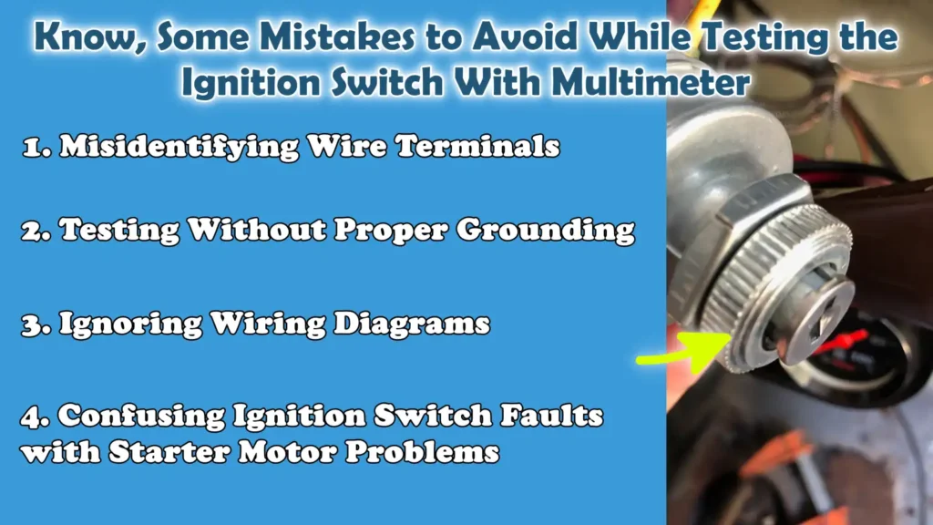
1. Misidentifying Wire Terminals
One of the most common mistakes when testing an ignition switch is becoming confused regarding the wire terminals located inside the connector.
Each wire serves a specific function such as: battery input, accessory output, ignition output, or starter signal, and interchanging them can lead to completely erroneous results.
As wire colors and pin layouts vary across different vehicles, relying solely on color codes rather than performing a proper identification can be misleading.
This often results in testing the wrong circuit and mistakenly assuming that the ignition switch is faulty, when in reality, it is functioning correctly.
2. Testing Without Proper Grounding
A solid ground connection is essential for accurate voltage testing; neglecting this step can lead to incorrect readings.
If the multimeter’s black probe is not connected to a clean and stable ground point, readings may fluctuate or display incorrect values.
This can make a perfectly functional ignition switch appear defective, or conversely, allow actual electrical issues to go undetected.
A proper ground ensures that the electrical circuit is correctly completed during testing, a prerequisite for reliable diagnostics.
3. Ignoring Wiring Diagrams
Skipping the wiring diagram is another serious error that can cause confusion during the testing process.
Without it, determining which terminal connects to which circuit becomes difficult, particularly in modern vehicles equipped with complex electrical systems.
Wiring diagrams provide precise information regarding pin locations, wire functions and circuit flow.
Ignoring this guide increases the risk of incorrect probing, misdiagnosis and the unnecessary replacement of components.
4. Confusing Ignition Switch Faults with Starter Motor Problems
Many people mistakenly assume that a “no-crank” condition (when the engine fails to turn over) invariably indicates a faulty ignition switch; however, this is not always the case.
If the ignition switch is delivering the correct voltage in the “START” position, yet the engine still fails to start, the issue may lie with the starter motor, solenoid, relay, or even the battery connections.
Confusing these symptoms can lead to the replacement of the wrong component, leaving the actual problem unresolved.
Proper, step-by-step diagnostic testing helps to clearly distinguish between faults within the ignition switch and those within the starter system.
Read More:
How to Solve the Common Problems: If the Ignition Switch is Functioning
Even, there’s modern research that confirms that ignition system faults can be detected through the voltage behavior analysis, as the abnormal switching patters and unstable electrical signals actually indicates that component is failed or worn out, that’s why when you use the multimeter for testing purpose then it gives you really reliable results so that you can safely diagnose the method for identifying the ignition switch issues before any deeper engine disassembly.[¹]
1. Checking the Battery Condition
If tests performed on the ignition switch indicate that voltage readings are normal across all key positions, the next step is to check the battery, as it serves as the primary power source for the entire system.
A weak or deteriorating battery may register some voltage, but it often fails to deliver sufficient current to start the engine.
This frequently manifests as problems such as slow cranking, clicking sounds, or the engine failing to start at all.
Checking the battery voltage under load helps confirm whether it possesses sufficient power to drive the starter motor and all associated electrical systems.
2. Checking the Starter Relay
When the ignition switch is functioning correctly, the starter relay becomes the next critical component to inspect.
The relay acts as a bridge between the ignition switch and the starter motor; if it malfunctions, the starter motor will not receive the signal required to crank the engine.
A faulty relay can cause intermittent starting issues, or prevent the engine from cranking entirely, even if the ignition switch is sending the correct voltage.
Listening for clicking sounds and verifying the operational status of the relay helps ensure that it is functioning properly.
3. Testing the Ignition Fuse and Relay
The fuse and relay associated with the ignition circuit should also be checked, as they serve to protect the system from electrical overloads.
A blown (faulty) ignition fuse can prevent power from reaching the engine’s main systems, while a defective relay can interrupt the flow of voltage, even if the ignition switch itself is in good working condition.
These components should undergo a visual inspection and their continuity, or proper switching behavior, must be tested to ensure that they are not impeding the flow of electricity within the circuit.
4. Checking the Wiring Harness for Faults
If all major components are found to be in good working order during testing, the wiring harness becomes the final area to inspect.
Damaged, corroded, or loose wiring can lead to voltage drops or cause intermittent electrical issues that are difficult to diagnose.
Common problems include damaged insulation (the outer layer of the wire), loose connectors, or corrosion at terminal points.
Even a minor nick in the wiring can interrupt the signal between the ignition switch and the starter system, resulting in misleading symptoms that may appear to be a component failure.
Carefully examining the wiring harness helps identify hidden faults that might otherwise go undetected during standard electrical checks.
So, When to Replace the Ignition Switch
1. Symptoms Indicating the Need for Replacement
The ignition switch should be replaced when diagnostic testing and real-world symptoms clearly point to an internal malfunction.
Common symptoms include a lack of power in specific key positions, intermittent flickering of dashboard lights, sudden engine stalling while driving, or the engine failing to start at all, even if the battery and starter are in good condition.
Another definitive indicator is observed during voltage testing, where fluctuations in output are clearly evident, for instance, if the reading is normal in the ACC position but is absent or unstable in the ON or START positions.
These patterns typically signal wear on the internal contacts, which are no longer capable of reliably regulating the flow of electricity.
2. Considering Temporary vs Permanent Repairs
In some cases, drivers may find temporary relief from ignition-related issues by adjusting the key position or restarting the vehicle multiple times; however, this is not a genuine solution.
These temporary measures often work when the switch’s internal contacts are only slightly worn and still manage to make intermittent contact.
However, as the issue of internal wear within the switch does not resolve itself, the problem typically recurs, and often worsens over time.
A permanent solution requires replacing the ignition switch, rather than relying on temporary fixes that could fail abruptly at any moment.
3. The Importance of Proper Installation
Proper installation of a new ignition switch is crucial for the safe and reliable operation of the vehicle.
Even a brand-new switch can cause problems if it is not properly aligned with the ignition cylinder or if the wiring connector is not securely attached.
Improper installation can lead to issues such as the vehicle failing to start, accessories malfunctioning, or electrical short circuits.
It is also essential to ensure that all connectors are clean, securely fastened and correctly connected according to the wiring diagram.
A properly installed ignition switch restores precise voltage control across all key positions, thereby ensuring reliable engine starting and the proper functioning of electrical components.
Conclusion – How to Test Ignition Switch with Multimeter
So, most of the time even single voltage test shows you the real problem and you can confirm that the ignition system is healthy or not.
Instead, it may function correctly in certain situations while failing in others, leading to problems such as a no-start condition, intermittent power loss, or a dashboard blackout, even if the battery is functioning perfectly.
For this reason, performing a proper diagnosis using a multimeter is crucial; rather than relying on guesswork based solely on symptoms, this tool enables you to clearly trace the flow of voltage at every stage of the ignition process.
By systematically testing the battery input, ACC output, ON output and START signal, you can accurately distinguish a faulty ignition switch from other common issues such as: a weak battery, a defective starter relay, or faulty wiring.
This diagnostic approach is widely utilized in automotive repair because it is both logical and precise, helping to prevent the unnecessary replacement of components.
Now, that’s all about this one and you can comment down below regarding this guide.
Frequently Asked Questions
FAQ 1: What are the common symptoms of a faulty ignition switch?
Answer: A faulty ignition switch often exhibits specific electrical symptoms, although they may appear somewhat confusing at first glance. The most common symptoms include: the car failing to start despite a healthy battery, dashboard lights failing to illuminate, or accessories such as: the radio and power windows, functioning intermittently. In some cases, the engine may start sometimes but not others; this is a clear indication that the internal contacts within the switch have worn out. Another common symptom is receiving no response whatsoever when turning the key, even if the battery is fully charged.
FAQ 2: Can a faulty ignition switch drain the battery?
Answer: Yes, a faulty ignition switch can sometimes drain the battery, though this typically occurs indirectly. If the switch malfunctions in such a way that the accessory or ignition circuits remain partially active even when the key is in the ‘OFF’ position, they can gradually deplete the battery’s power. This is not a very common occurrence, but it can happen with worn-out or defective switches. In most cases, the cause of a drained battery lies with another electrical fault; therefore, it is essential to test any component before replacing it.
FAQ 3: How can I determine if the ignition switch is the actual cause of the problem?
Answer: The best way to confirm a problem with the ignition switch is to test it using a multimeter. If the battery input is normal, but no output is detected at the ACC, ON, or START positions, or if the output is unstable, there is a very high probability that the switch itself is defective. If all outputs appear correct, yet the car still fails to start, the problem likely lies elsewhere such as: with the starter motor, relays, or wiring. A step-by-step diagnostic approach eliminates the need for guesswork and ensures an accurate diagnosis.
FAQ 4: Can a car start even with a faulty ignition switch?
Answer: In some instances, a car may still start despite having a faulty ignition switch, but it will not be reliable. The vehicle may start intermittently, or it could suddenly stall while driving due to a lack of power in the ignition circuit. If voltage is still flowing correctly from the ‘START’ position, the engine may crank; however, other systems such as: the fuel or ignition systems, may subsequently malfunction. Therefore, if ignition switch issues are not addressed promptly, they often tend to worsen over time.
FAQ 5: Is it safe to test an ignition switch at home?
Answer: Yes, provided you adhere to basic safety guidelines, testing an ignition switch at home is generally safe. Using a multimeter does not require cutting any wires and most diagnostic checks are performed by testing the connector pins from the rear. However, you must exercise caution to avoid short circuits and always ensure proper grounding when measuring voltage. By working carefully and utilizing a wiring diagram to understand the circuit layout, most users can perform this procedure safely and accurately.
FAQ 6: Do I need to remove the ignition switch to test it?
Answer: Not always. In most cases, you can test the ignition switch without removing it, simply by accessing the connector and checking the voltage at the pins. This method is faster and avoids the need to unnecessarily disassemble components. However, if you need to perform a continuity test, or if accessing the connector proves difficult, you may need to partially remove the switch. Most professional diagnostic procedures begin with a voltage check while the components are still in their original positions.
References:
[1] Optimization of the Ignition System Diagnostics Methodology
https://www.mdpi.com/2624-8921/8/4/71

Hello Folks, Dean Shali here to help you out to solve the problems with your lovely vehicle, as i have lots of experience and knowledge about automotive industry as i woks directly with the customers and repair vehicles and i love to help the people to keep their cars safe and running smoothly.