Written By: Dean Shali
Fact Checked By: Sabré Cook
Reviewed By: Tamara Warren
Basically, most of the time ABS warning lights are not caused by the sensor itself, but there could be more chances of having “WIRING FAULTS” that actually interrupts critical signals forward.
Yes, modern vehicles relies on the advanced safety systems that helps the drivers to stay in control and because of the safety feature: the Anti-Lock Braking Systems (ABS) is one of the most important among them.
As, ABS monitors the speed of each wheel and adjusts the brake pressure in the matter of milliseconds that’s how it prevents skidding, that becomes really helpful during the sudden stops or when you have to deal with slippery conditions.
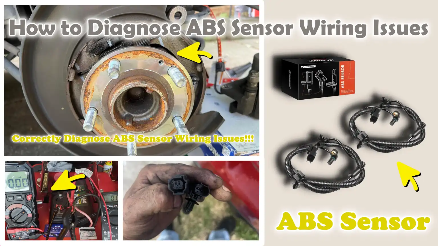
So, at the center of this system there’s wheel speed sensors and the wiring that literally connects them to the control module.
But, the thing is many car owners just assume that ABS warning light only means a failed sensor itself, but diagnosis often shows that there’s wiring faults such as: corrosion, broken insulation or loose connectors that’s why diagnosis is really important before any assumption.
Now, in this guide you’ll learn How to Diagnose ABS Sensor Wiring Issues so that you can quickly identify the actual problem and restore that braking reliability again.
Understand, What is an ABS Sensor and How Does Its Wiring Work?
The Anti-lock Braking System (ABS) continuously tracks how fast each wheel is rotating by utilizing wheel speed sensors and their associated wiring and it transmits this information to the control module.
By adjusting brake pressure in real-time, this system helps prevent the wheels from locking up during hard braking.
The sensor itself does not operate in isolation; it relies on clear and stable electrical signals transmitted via a wiring harness.
If the wiring is damaged, loose, or corroded, the signal may become weak, inaccurate, or cease entirely.
Therefore, for accurate diagnostics and the safe operation of the vehicle, it is crucial to understand both the sensor and its accompanying wiring.
1. The Role of the ABS Wheel Speed Sensor
ABS wheel speed sensors are responsible for measuring the rotational speed of each wheel.
They detect how fast a wheel is spinning and transmit this data to the control module multiple times per second.
This information helps the system identify when a wheel is about to lock up during braking.
When this occurs, the system immediately adjusts the brake pressure to ensure that the wheel continues to rotate and traction is maintained.
Without accurate data from the sensors, the ABS system cannot function correctly, which could result in a loss of vehicle control during sudden braking maneuvers.
2. How Do Signals Reach the Control Module?
The signals generated by the ABS sensors travel from each wheel to the ABS control module via dedicated wiring.
This wiring serves as a communication pathway, transmitting electrical signals without interruption.
The control module interprets these signals and makes immediate decisions by comparing the speeds of all the wheels.
If the wiring suffers from wear and tear, excessive resistance, or a poor connection, the signals will fail to reach the module accurately.
Even a minor obstruction can lead to inaccurate readings, trigger warning lights, or cause the entire system to shut down completely.
3. Types of ABS Sensors
Modern vehicles utilize two primary types of ABS sensors; although each sensor operates in a slightly different manner, both rely heavily on proper wiring to ensure their functionality.
Passive/Magnetic ABS Sensors
Passive sensors generate a small electrical voltage using a magnetic coil; this voltage is produced as a toothed ring rotates in conjunction with the wheel.
This voltage fluctuates according to the wheel’s speed and is transmitted to the control module via the wiring.
These sensors do not require an external power supply; however, they generate weaker signals at low speeds.
Consequently, any wiring-related issue such as: corrosion or increased electrical resistance, as it can easily distort or weaken the signal, making it even more difficult to obtain accurate readings.
Active/Hall-Effect ABS Sensors
Active sensors employ electronic components and require a power supply directly from the vehicle.
They generate a digital signal that remains highly accurate and reliable, even at low speeds.
These sensors transmit distinct “on” and “off” signals that the control module can easily interpret.
However, because they rely on both power and ground connections, wiring-related issues such as: low voltage, poor grounding, or faulty insulation, as it can prevent the sensor from functioning altogether.
4. The Importance of Wiring Integrity for Signal Accuracy
The accuracy of an ABS system depends significantly on the condition of its wiring.
Clean and stable wiring ensures that the signals transmitted by the sensors reach the control module without any interruption.
Issues such as broken wires, loose connectors, moisture intrusion, or corrosion can degrade signal quality or interrupt it entirely.
This can lead to inaccurate readings, trigger warning lights, or cause the ABS to cease functioning.
In many instances, the sensor itself is operational, but wiring issues prevent it from transmitting data correctly.
Maintaining the wiring in good condition is crucial to ensure reliable braking performance and overall vehicle safety.
Know, About The Common Symptoms of ABS Sensor Wiring Problems
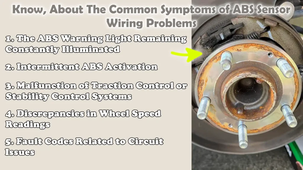
ABS sensor wiring issues often manifest as specific warning signs, signals that many drivers notice but do not fully understand.
These problems typically stem from damaged wires, loose connections, or corrosion, which disrupt the electrical signals traveling between the wheel speed sensors and the control module.
As the ABS system relies on precise and consistent data, even a minor wiring fault can trigger a cascade of symptoms.
These symptoms may appear suddenly or occur intermittently, making it even more challenging to pinpoint the root cause of the problem.
A thorough understanding of these signs helps in quickly diagnosing the underlying issue and avoiding the unnecessary replacement of components.
1. The ABS Warning Light Remaining Constantly Illuminated
One of the most common and easily recognizable symptoms is the ABS warning light remaining constantly illuminated on the dashboard.
This light activates whenever the system detects a fault that interferes with its normal operation.
In cases involving wiring issues, the control module may stop receiving accurate signals from one or more wheel speed sensors.
When this occurs, the system disables the ABS as a safety precaution and stores a specific “fault code.”
Although the vehicle’s brakes may still function normally, the “anti-lock” feature will not engage during emergency braking situations.
A continuously illuminated warning light often indicates a persistent issue such as: a severed wire or a loose connector.
2. Intermittent ABS Activation
Intermittent ABS activation is a symptom in which the system suddenly engages, even when you are braking normally on a dry road surface.
This typically happens when a wiring fault causes the signals transmitted by the sensors to become unstable or erroneous.
For instance, a loose wire might intermittently disconnect and then reconnect; Consequently, the control module begins to receive wheel speed data in a suddenly altered form.
The system may interpret this as wheel slippage and, as a result, unnecessarily activate the ABS.
This may manifest as vibrations in the brake pedal or strange noises, potentially confusing the driver and eroding their confidence in the vehicle’s braking performance.
3. Malfunction of Traction Control or Stability Control Systems
Many modern vehicles utilize the same wheel speed sensors and wiring harnesses for their ABS, traction control and stability control systems.
When a fault develops within this wiring, it does not merely affect the ABS; it can also prevent other interconnected systems from functioning.
Drivers may observe warning messages or indicator lights associated with the traction control or stability control systems, in addition to the ABS warning light.
These systems rely on accurate wheel speed data to maintain vehicle traction and stability, particularly during acceleration or while cornering.
If the wiring fails to transmit reliable signals, the system may deactivate these features to prevent erroneous operation.
4. Discrepancies in Wheel Speed Readings
Wiring issues frequently lead to discrepancies or inaccuracies in wheel speed readings.
This can be detected during diagnostic testing using a scan tool, which displays live data from each individual wheel.
A faulty wire may cause a specific sensor to report a speed that does not align with the readings from other sensors, even when the vehicle is traveling at a constant speed.
In some instances, readings may suddenly drop to zero or fluctuate erratically without any apparent cause.
These irregular signals make it difficult for the control module to accurately compare wheel speeds, a process that is absolutely essential for the proper functioning of the ABS.
5. Fault Codes Related to Circuit Issues
When the ABS system detects a problem within its wiring, it stores specific fault codes that aid in identifying the issue.
These codes often point to problems such as open circuits, short circuits, or signal irregularities.
An open circuit indicates that the path of electrical current has been interrupted, whereas a short circuit signals that the current is flowing through an unintended path.
These conditions typically arise due to damaged insulation, exposed wires, or loose connections.
Reading these fault codes with the aid of an appropriate diagnostic tool serves as a starting point for troubleshooting, making it easier to determine whether the problem lies in the wiring, the connectors, or the sensor itself.
Know, The Main Causes of ABS Sensor Wiring Failure
Malfunctions in ABS sensor wiring are typically not caused by the sudden failure of a specific component, but rather by real-world operating conditions that degrade the wiring over time.
The wiring connecting the wheel speed sensors to the control module is constantly exposed to heat, moisture, vibration and the dynamic movements of the suspension and steering systems.
For this reason, it is one of the most vulnerable parts of the braking system.
Even a minor issue in the wiring can disrupt the electrical signal, degrade its quality, or interrupt it entirely.
Understanding the primary causes helps in diagnosing the problem quickly and prevents the recurrence of the same issue after repairs.
1. Physical Damage – Road Debris, Heat, Corrosion
Physical damage is one of the most common causes of ABS wiring failure.
Wiring located near the wheels is exposed to stones, dust, water, road salt and other debris, which can strike or chafe against it while the vehicle is in motion.
Over time, this can wear down the insulation, exposing the internal wires.
Heat generated by nearby components such as: the brakes and engine, as it can also degrade the insulation, causing it to become brittle and increasing the likelihood of cracking.
Moisture and road salt can lead to corrosion, particularly at connection points, resulting in increased electrical resistance and reduced signal quality.
These conditions gradually damage the wiring until the signal becomes unreliable or ceases entirely.
2. Broken or Frayed Wires
Broken or frayed wires are often the result of constant movement and vibration within the suspension system.
As the vehicle travels, the wiring harness repeatedly flexes, particularly around the wheels and steering components.
Over time, this can cause the metal inside the wire to weaken and break, even if the outer insulation still appears normal.
In other cases, the insulation may wear down, exposing the wire and making it susceptible to abrasion.
A broken wire creates an open circuit, meaning the signal fails to reach the control module entirely.
Worn wires can lead to intermittent issues, where the connection works at times and fails at others.
3. Loose or Corroded Connectors
Connectors are critical points where the wiring interfaces with sensors and the main harness.
If these connectors become loose, the electrical connection becomes unstable, potentially causing signal drops or fluctuations.
Corrosion inside the connectors is another common issue, typically caused by moisture ingress into the connection.
This results in deposits forming on the metal terminals, which obstruct or weaken the flow of electricity.
Even minor corrosion can increase resistance and degrade signal quality.
Loose or corroded connectors often cause intermittent faults that are difficult to diagnose, as the problem tends to appear and disappear unpredictably.
4. Short Circuits or Open Circuits
Electrical faults such as short circuits and open circuits are direct causes of wiring failure.
An open circuit occurs when a wire breaks completely, bringing the flow of electricity to a complete halt.
A short circuit occurs when electrical current flows through an unintended path; this is often caused by damaged insulation, allowing wires to come into contact with one another or with the vehicle’s body.
Both of these conditions prevent the ABS system from receiving accurate data from the sensors.
Short circuits can also blow fuses or damage other components, while open circuits typically result in a complete loss of signal from the affected sensor.
5. Prior Poor Repair Work
Improperly executed repair work is another major cause of recurring issues with ABS wiring.
If wiring repairs are performed incorrectly such as: by twisting wires together without proper insulation or using substandard connectors, the repairs are prone to premature failure.
Furthermore, improper routing of the wiring following a repair can cause the wires to chafe against moving parts or expose them once again to heat and moisture.
In some instances, the repair fails to fully restore the original electrical properties of the wires, resulting in weak or unstable signals.
To ensure the long-term reliability of the wiring system, it is crucial to employ proper repair techniques, including secure connections, adequate insulation and safe routing of the wires.
Tools
| Tools | Why It Is Needed | How to Use It |
|---|---|---|
| OBD2 Scanner with ABS Capability | This tool reads fault codes stored within the vehicle’s system. It precisely identifies which specific wheel or circuit is experiencing an issue, thereby saving time and eliminating the need for guesswork. Without it, you would essentially be shooting in the dark. | Connect the scanner to the vehicle’s OBD2 port, which is typically located beneath the dashboard. Turn on the ignition and scan for ABS codes. Note the codes and monitor the live data stream to compare wheel speeds. Identify the specific wheel that is not transmitting a signal or is providing an erroneous reading. |
| Digital Multimeter | This tool measures voltage, resistance and continuity within the wiring. It helps determine whether a wire is broken, short-circuited, or functioning correctly. It is an essential tool for assessing the overall health of the electrical system. | To check for a broken wire, set the multimeter to continuity mode. Use resistance mode to test the sensor circuit. Use voltage mode to verify that power is reaching the sensor. Place the probes at both ends of the wire or connector pin. |
| Wiring Diagram for Your Vehicle | This tool illustrates the correct routing of wires, the locations of connectors and pin configurations. It helps you understand exactly where to perform tests, thereby preventing errors. Without it, there is a risk of testing the wrong wires. | Locate the specific ABS wiring diagram corresponding to your vehicle’s make and model. Identify the sensor wires, connector pins and ground points. Follow the diagram step-by-step to accurately trace the circuit while performing tests. |
| Jack and Jack Stands | These tools assist you in safely lifting the vehicle, making it easier to access the wheel sensors and their associated wiring. Adopting the correct methodology is crucial for effective inspection and testing. Safety is the primary reason why these tools are indispensable. | Use a jack to lift the vehicle at the designated lifting points. Place jack stands beneath the frame to support the vehicle. Never rely solely on the jack. Once the vehicle has been lifted, remove the wheel, if necessary, to facilitate easy access to the sensors and wiring. |
| Test Light – Optional | A test light quickly determines whether power or ground is present in a circuit. For general diagnostics, it is easier to use than a multimeter and helps confirm the flow of electricity. | Connect the clip to a ground point and touch the probe to the wire or connector. If the light illuminates, it indicates that power is present. Use this tool to perform a quick check for power and ground before conducting a detailed examination with a multimeter. |
How to Diagnose ABS Sensor Wiring Issues – Perfect Method for Beginners
Adopting a clear and systematic approach is essential for diagnosing ABS sensor wiring issues, as the problem is often not apparent at first glance.
The objective is to follow a logical sequence, first identifying the potential fault and then verifying it through testing.
ABS systems rely on precise electrical signals; therefore, even a minor fault in the wiring can trigger significant problems, such as the illumination of a warning light or a complete system failure.
By following these steps sequentially, you can avoid guesswork, reduce repair time and ensure that you are addressing the root cause rather than unnecessarily replacing parts.
1. Scan for ABS Trouble Codes
The first step is to check for trouble codes stored within the system using an ABS-capable scan tool.
These codes provide invaluable information regarding which specific part of the system is affected.
In many cases, the code will point to a specific wheel or circuit such as: the front left or rear right wheel, helping you narrow down the area requiring inspection.
It is also crucial to understand the specific type of code being displayed.
An “open circuit” code often indicates a break or interruption somewhere in the wiring, whereas a “short circuit” code suggests that electrical current is flowing through an unintended path.
A “signal malfunction” code typically indicates that the data being transmitted is weak or erratic.
Reading and interpreting these codes provides you with a solid starting point for diagnosing the problem.
2. Conduct a Visual Inspection
Once the problematic area has been identified, the next step is to conduct a visual inspection of the wiring and connectors.
This step is simple yet critical, as many wiring issues can be detected without the need for any specialized tools.
Inspect the wiring harness for signs of damage, such as cuts, cracks, or worn insulation.
Pay particular attention to areas near the wheels, where the wiring is exposed to movement and rough road conditions.
Additionally, carefully check the connectors for dirt, moisture, or corrosion, as these can obstruct or weaken electrical connections.
A loose connector can also cause intermittent issues.
Addressing any visible problems at this stage often resolves the issue without the need for further testing.
3. Check Wiring Continuity
If no obvious damage is found, the next step is to check the wiring’s continuity (electrical connection) using a digital multimeter.
Continuity testing verifies whether electricity can flow from one end of the wire to the other.
To check the electrical path for continuity, place the multimeter probes on both ends of the wire, or on the connector terminals.
If the multimeter does not indicate continuity, it means there is a break somewhere in the wire, a condition known as an “open circuit.”
This type of fault completely prevents signals from reaching the control module and it must be repaired before the system can function correctly.
4. Check for Short Circuits
Once continuity has been confirmed, it is essential to check the wiring for short circuits.
A short circuit occurs when electricity flows through an unintended path, often caused by damaged insulation or contact with the vehicle’s metal components.
Use the multimeter to measure the resistance between the wire and the vehicle’s ground (earth) or other adjacent wires.
While resistance should not be extremely low, a reading indicating very low resistance suggests the presence of a short circuit.
Short circuits can send erroneous signals, trigger warning lights, or even damage vehicle components.
Identifying and rectifying these faults ensures that electrical signals travel along their intended paths.
5. Measure Sensor Voltage Signals
The next step involves measuring the voltage signals transmitted from the ABS sensor through the wiring.
This helps confirm whether the sensor and the associated wiring are functioning correctly in tandem.
Use a multimeter to check the voltage at the connector while the wheel is rotating, whether spun by hand or during a controlled test drive.
Compare this reading against the manufacturer’s specifications for your specific vehicle.
A weak or unstable signal may indicate resistance within the wiring, a poor connection, or minor internal damage.
An accurate voltage reading is crucial, as the control module relies on a clean signal to calculate wheel speed.
6. Perform a ‘Wiggle Test’ on the Wiring Harness
Intermittent wiring faults are often difficult to diagnose because they do not occur continuously.
The ‘wiggle test’ is a simple method for identifying such issues.
While monitoring the signal using a multimeter or a scan tool, gently wiggle or flex different sections of the wiring harness.
If the signal suddenly fluctuates, drops, or cuts out completely, it indicates a loose connection or a damaged internal wire within that specific section.
This test is particularly effective for detecting problems that manifest only when the vehicle is in motion, that is, when the wiring is subjected to constant vibration and movement.
7. Compare with Other Wheel Sensors
In the final step, the readings from the suspected faulty sensor are compared against the readings from sensors located on the vehicle’s other wheels that are functioning correctly.
This establishes a ‘reference point,’ making it easier to distinguish between normal and abnormal operation.
Use a ‘scan tool’ to view ‘live data’ or directly measure the signal and compare readings such as voltage or speed across the sensors.
If a specific sensor appears to behave differently from the others under identical conditions, it confirms that the fault lies within that particular circuit.
This type of comparative analysis helps pinpoint the root cause of the problem and ensures that you have accurately identified the issue at hand.
How to Distinguish Between a Faulty Sensor and a Wiring Issue
Distinguishing between a faulty ABS sensor and a wiring issue is crucial, as both can trigger identical warning lights and cause similar malfunctions in the braking system; however, the repair procedures for each are entirely different.
Many people instinctively replace the sensor first, but upon actual diagnosis, it is often revealed that the wiring was the root cause.
The key approach is to inspect both the sensor and the wiring in a simple, logical sequence to pinpoint the exact location of the fault.
A properly functioning sensor requires a clear electrical pathway to transmit accurate signals; therefore, if there is a fault in the wiring, even a perfectly functional sensor will cease to operate.
By performing a few basic checks, you can avoid guesswork and make an informed decision.
1. Checking Sensor Resistance and Wiring Continuity
The most reliable method for distinguishing between a faulty sensor and a wiring issue is to check the sensor’s resistance and the wiring’s continuity.
The sensor’s resistance indicates whether its internal components are functioning correctly.
You can measure this by connecting a multimeter to the sensor’s terminals and comparing the resulting reading against the specifications prescribed for your specific vehicle.
If the reading falls significantly outside the normal range, or if there is no reading at all, it is highly probable that the sensor itself is defective.
Conversely, checking the wiring’s continuity verifies whether the electrical pathway between the sensor and the control module remains intact.
By performing a continuity check, you can detect any breaks or interruptions within the circuit.
If the sensor tests positive but the wiring lacks continuity, it indicates that the problem lies with the wiring, not the sensor.
2. Comparing Signal Outputs
Another effective method involves comparing the signal outputs generated by the sensors.
As the wheel rotates, the sensor should produce a steady and consistent signal.
You can measure this signal using a multimeter or monitor it via a scan tool.
If the signal is weak, erratic, or entirely absent, it may indicate a faulty sensor or a wiring issue.
To pinpoint the root cause of the problem, you must determine exactly where the signal is being lost.
If the sensor produces a strong signal at its connector, but the signal weakens or disappears further down the wiring harness, the issue lies within the wiring.
Conversely, if the signal is already weak at the sensor itself, it is highly probable that the sensor is the source of the problem.
3. Swapping Sensors
Swapping sensors is a simple and practical technique that aids in diagnosing the true cause of a malfunction.
This involves removing the sensor from the wheel exhibiting the fault and installing it on a different wheel that is known to be functioning correctly.
If the problem follows the sensor to its new location, it clearly indicates that the sensor itself is defective.
However, if the problem persists at the original location even after swapping the sensor, then the wiring or connector associated with that specific wheel is the root cause of the issue.
This method is effective because it eliminates the need for guesswork; instead, it accurately identifies the fault through direct comparison.
4. Utilizing Live Data from a Scan Tool
Monitoring live data via a scan tool is one of the most precise methods for diagnosing a problem.
When the vehicle is in motion, or even when the wheels are being rotated manually, the scan tool displays real-time wheel speed readings from all the sensors simultaneously.
By comparing these readings, you can immediately identify whether a specific wheel is providing erroneous data or no data at all.
If a sensor fails to provide any reading whatsoever, it indicates that either the sensor itself is defective or a wire is broken.
To conclusively verify this, you should cross-reference these results with other diagnostic methods, such as continuity and resistance checks.
If the data intermittently appears and disappears, or changes abruptly when the wiring is manipulated, it is a definitive indication of a wiring issue.
Live data allows you to observe how the system actually behaves during operation, thereby making it significantly easier to pinpoint the root cause of the problem.
How to Perform Advanced Diagnostic Techniques
When basic inspections fail to clearly identify a problem, advanced diagnostic techniques help you visualize exactly how the ABS system is functioning.
These methods focus on signal quality, connection stability and proper electrical supply, factors that are critical for the correct operation of the ABS.
Modern ABS systems react with great speed and rely on clear, consistent signals; therefore, utilizing these techniques allows for the detection of even minor anomalies that might otherwise go unnoticed during standard inspections.
Employing these methods aids in pinpointing the root cause of a malfunction, thereby eliminating the need for repetitive repairs.
1. Using an Oscilloscope for Waveform Analysis
An oscilloscope is an invaluable tool that allows you to visualize the actual electrical signals generated by ABS sensors in the form of waveforms.
Unlike a multimeter, which merely displays a single numerical value, an oscilloscope illustrates how the signal changes over time.
For passive sensors, the waveform typically appears as a smooth, repetitive pattern, with its amplitude (height) increasing as the wheel speed rises.
For active sensors, the waveform manifests as a distinct digital signal that alternates between high and low voltage levels.
A healthy signal should be stable and uniform, devoid of any sudden drops or irregular shapes.
If the waveform appears distorted, weak, or contains missing segments, it often indicates underlying wiring issues such as: excessive resistance, poor connections, or open circuits.
This technique is highly effective because it reveals problems that would otherwise remain undetected through standard voltage or resistance checks.
2. Inspecting ABS Module Connections
The ABS control module functions like a central processing unit, receiving signals from all the sensors that report wheel speed; therefore, it is crucial that its connections remain secure and clean.
Over time, the connectors attached to the module may develop issues such as looseness, corrosion, or dirt accumulation.
These problems can disrupt communication between the sensors and the module, even if the wiring near the wheels is in good condition.
Inspecting the module connections involves checking the connector pins for any defects, ensuring they are neither bent nor dislodged, and verifying that the connector is fully seated within its housing.
Poor connections at the module can cause multiple sensors to fail simultaneously, potentially leading to confusion during the diagnostic process.
A robust connection at this interface is essential for accurate signal processing.
3. Checking the Integrity of Ground and Power Supply
ABS sensors and the control module rely on stable power and ground connections to function correctly, particularly in systems equipped with active sensors.
If the power supply is weak or the ground connection is compromised, the sensors may fail to transmit accurate signals, even if the sensors themselves are not defective.
The inspection process involves measuring the voltage supply at the sensor connector to ensure it aligns with the vehicle’s specified values.
It also entails checking the ground path to verify that resistance is minimal and that the connection to the vehicle’s chassis is secure.
Any voltage drop or increase in resistance can adversely affect signal quality and result in erroneous readings.
Reliable power and ground connections serve as the foundation for the entire system; without them, accurate diagnosis is impossible.
Know, The Common Mistakes During Diagnosing the ABS Sensor Wiring Issues to Avoid Them
Diagnosing ABS sensor wiring issues requires patience and a systematic approach; however, many problems arise because essential steps are skipped or performed in haste.
These errors often lead to misdiagnosis, unnecessary parts replacement and recurring malfunctions.
As ABS systems rely on precise electrical signals, even a minor oversight can prevent you from identifying the true root cause of the problem.
Understanding the most common mistakes saves time, reduces repair costs and ensures that the system is fixed correctly the very first time.
1. Replacing the Sensor Without Checking the Wiring
One of the most common mistakes is failing to inspect the associated wiring before replacing an ABS sensor.
Many drivers, and even some technicians, assume that when the ABS warning light illuminates, the sensor itself is the primary culprit.
However, in many cases, the wiring is the actual source of the problem.
If a wire is broken, corroded, or exhibits excessive resistance, installing a new sensor will be futile, as the signal will not reach the control module correctly.
This leads to frustration and unnecessary expense.
Checking the wiring before replacing the sensor ensures that you are addressing the actual problem, rather than merely guessing.
2. Ignoring Intermittent Faults
Intermittent faults are issues that appear sporadically and then disappear, making them particularly difficult to diagnose.
Many people overlook these faults because the warning light may turn off on its own, or the system may occasionally appear to function normally.
However, these issues often indicate loose connections, faulty wiring, or internal wear and tear that manifest only under specific conditions such as: when the vehicle is in motion or when ambient temperatures are fluctuating.
Ignoring these warning signs can cause the problem to worsen over time, potentially leading to a complete system failure.
Proper diagnostics should always involve methods such as monitoring live data and performing movement tests to uncover these hidden faults.
3. Failure to Thoroughly Inspect Connectors
Connectors are critical components within the ABS wiring system, yet they are frequently overlooked during the diagnostic process.
A connector may appear intact on the outside, but it could harbor internal corrosion, dirt, or loose terminals, all of which compromise the electrical connection.
Even a trace of corrosion can increase electrical resistance and attenuate the signal.
The presence of moisture inside a connector can also lead to unstable readings.
By failing to carefully inspect connectors, it becomes impossible to identify the true root cause of the problem.
Taking the time to clean, inspect and properly secure connectors is essential for accurate diagnostics.
4. Ignoring Wiring Diagrams
Ignoring wiring diagrams is another major error that can lead to confusion and inaccurate diagnostic results.
Every vehicle features a unique wiring layout, providing comprehensive details regarding wire colors, connector locations and circuit routing.
Without a diagram, it is easy to test the wrong wire or misinterpret the results.
This can lead to unnecessary repairs or, conversely, allow a fault to go undetected.
A wiring diagram provides a clear roadmap of the system, helping you understand where to conduct tests and what results to expect.
Using this resource ensures the accuracy of your diagnosis and confirms that you are on the right path to identifying and resolving the problem.
Understand, When to Repair and When to Replace Wiring?
Deciding whether to repair or replace ABS sensor wiring depends on the severity of the damage and how long the repair can be expected to remain reliable.
ABS wiring transmits critical signals that help control the braking system; therefore, any repair must be robust, stable and protected from heat, moisture and vibration.
Hasty repairs that fail to fully restore the integrity of the wire can lead to recurring malfunctions and create unsafe driving conditions.
The goal is to restore the wiring as closely as possible to its original condition, ensuring that signal transmission remains accurate and consistent under all driving conditions.
And, there’s modern research that shows that ABS faults diagnosis is not just about identifying the possibly failed components but it is about analyzing the entire signal system, that’s why wiring issues should be checked as well because they can create inconsistencies that mimics sensor failure as well, that’s why structured diagnostic methods are really important to correctly identify the actual root cause and avoid misdiagnosis as well.[¹]
1. Methods for Repairing Minor Damage
If the issue is minor and confined to only a small section of the wire, minor wiring damage can typically be repaired.
This includes cases where the insulation is slightly chafed, a single wire is severed, or there is minor corrosion on a connector.
The correct procedure involves removing the damaged section and splicing the wire back together using appropriate techniques, such as soldering or high-quality crimp connectors.
Once the connection is established, it should be sealed using heat-shrink tubing or suitable insulation to protect it from moisture and dirt.
It is also essential to secure the repaired wire so that it does not vibrate or chafe against other vehicle components.
If executed correctly, a minor repair can fully restore the wiring’s functionality and ensure its long-term durability.
2. When Replacing the Entire Wiring Harness Is Necessary
Replacing the entire wiring harness becomes necessary when the damage is extensive, spread across multiple locations, or compromises the overall structural integrity of the wiring system.
This includes situations where the wires are severely degraded, the insulation exhibits cracks or defects in multiple places, or corrosion has spread throughout the connectors and wiring.
If malfunctions persist even after repairs, it often indicates that the internal wiring has sustained deep-seated damage that cannot be rectified through standard repair methods.
Replacing the entire harness ensures that all connections are new, properly sealed and capable of withstanding the vehicle’s normal operating conditions.
Although this process requires more time and effort, it provides a more reliable and long-lasting solution.
3. Considering Cost vs Reliability
When choosing between repairing and replacing, it is essential to strike a balance between cost and reliability.
Repairing a small section of the wiring is typically cheaper and faster; however, to prevent future issues, the repair must be executed correctly.
A substandard repair can fail again, potentially leading to increased expenses down the line.
Replacing the entire harness entails a higher initial cost, but it delivers superior long-term reliability and significantly reduces the likelihood of recurring problems.
For critical systems such as the ABS, reliability is paramount, as it has a direct impact on safety.
In many instances, investing more in a proper and durable solution is preferable to saving money on a temporary fix that may not last.
Great Safety Tips During Diagnosis
When working on ABS sensor wiring, prioritizing safety is paramount; after all, you are simultaneously working on a raised vehicle and a sensitive electrical system.
Many accidents that occur during diagnosis are not the result of complex repairs, but rather stem from a disregard for basic safety precautions.
The vehicle must be stable, the electrical system handled with care and all tasks executed in a controlled and organized manner.
Taking a few extra minutes to adhere to proper safety protocols can prevent serious injury, safeguard vehicle components from damage and ensure accurate diagnostic results.
1. Proper Vehicle Lifting Techniques
Before accessing the wheel speed sensors and their surrounding wiring, it is crucial to lift the vehicle correctly.
Always lift the vehicle on a level, solid surface to ensure stability.
Utilize only the lifting points recommended by the vehicle manufacturer to ensure the chassis can safely support the vehicle’s weight.
After lifting the vehicle with a jack, do not forget to provide additional support by placing jack stands beneath sturdy frame components.
Never rely solely on the jack, as it may fail or lose pressure.
Once the vehicle is supported, gently rock it to verify its stability before beginning work underneath it or around the wheels.
Lifting the vehicle safely not only ensures your personal safety but also allows you to perform your work with complete confidence and precision.
2. Avoiding Electrical Shorts
Avoiding electrical shorts is of utmost importance when inspecting ABS wiring, as short circuits can damage components or create hazardous conditions.
Short circuits frequently occur when exposed wires come into contact with metal components of the vehicle, or when test probes are used improperly.
To prevent this, always ensure, before initiating any testing, that the insulation (protective layer) on the wires is completely intact.
Use only the appropriate tools equipped with insulated handles and avoid simultaneously touching multiple terminals with the metal parts of the tools.
When using a multimeter or test light, connect it with care and strictly adhere to the correct testing procedures.
Keeping the workspace clean and dry also minimizes the risk of accidental contact, which could lead to a short circuit.
3. Disconnecting the Battery When Necessary
In certain situations, particularly when performing wiring repairs or handling connectors, disconnecting the battery is a crucial safety precaution.
Disconnecting the battery eliminates the possibility of accidental electrical flow, thereby safeguarding both you and the vehicle’s electronic systems.
This is specially beneficial when repairing damaged wires, replacing connectors, or whenever there is a risk of wires accidentally coming into contact with one another.
However, for specific diagnostic tests (such as checking for voltage or “live signals”), it is necessary for the battery to remain connected.
In such instances, exercising extra caution is paramount to prevent errors.
Knowing when to disconnect the battery and when to keep it connected ensures that you can work on the ABS system safely and effectively.
How to Prevent ABS Wiring Problems in the Future
Preventing ABS wiring problems from occurring is far easier and less expensive than repairing them after they have failed.
The wiring connecting the wheel speed sensors is subjected to harsh conditions, such as heat generated by the brakes, constant movement of suspension components, water, dirt and road salt.
Over time, these conditions can degrade the insulation, loosen connections and compromise signal quality.
By adopting a few simple preventive measures, you can safeguard the wiring, maintain the accuracy of sensor signals and avoid warning lights or system malfunctions.
Effective prevention not only enhances reliability but also ensures that the ABS system responds correctly during emergency braking, precisely when it is needed most.
1. Regular Inspections
Regular inspection of ABS wiring is one of the most effective methods for preventing problems.
Checking the wiring during routine maintenance allows you to detect early signs of damage before they escalate into serious malfunctions.
Pay particular attention to the wiring near each wheel, where the risk of exposure to movement and external elements is highest.
Issues such as minor cracks in the insulation, slight corrosion on connectors, or loose connections can be remedied with minimal effort if caught in their early stages.
Regular inspections also help ensure that the clips and mounts securing the wiring remain in place, thereby preventing unnecessary movement.
Early detection ensures that the system continues to function correctly and helps avoid sudden, unexpected failures.
2. Proper Wiring Routing and Securing
Proper routing and securing of the wiring are essential for its long-term durability.
ABS wiring must strictly adhere to the original routing path designed by the manufacturer, ensuring that it remains clear of heat sources, sharp edges and moving components such as suspension arms and tires.
If the wiring is not routed correctly, it may rub against other parts and eventually wear through over time.
Securing the wiring with clips or fasteners keeps it stable and minimizes the stress caused by vibration and movement.
Properly secured wiring maintains a stable connection and reduces the risk of internal damage, a type of fault that is often difficult to diagnose.
3. Protection Against Moisture and Dirt
Moisture and dirt are primary causes of damage to wiring, particularly in areas located near the wheels.
Water, mud and road salt can infiltrate connectors and cause corrosion, leading to increased electrical resistance and weakened signals.
Protecting connectors with proper seals and ensuring they are securely fastened helps prevent moisture ingress.
Regularly cleaning the areas surrounding the wiring removes accumulated dirt, which could otherwise trap moisture.
In some cases, using protective covers or sleeves over exposed wiring provides an additional layer of protection.
Keeping the wiring clean and dry ensures stable signal transmission, allowing the ABS system to function reliably under all driving conditions.
Read More:
- How to Test Electronic Brake Module (EBCM)
- How to Fix Parking Brake Dragging
- How to Adjust Parking Brake Cable
- How to Check Parking Brake Cable Tension
- How to Fix Brakes Dragging While Driving
- How to Diagnose Brake Dragging Issue
- How to Fix Internal Master Cylinder Leak
- How to Test Brake Master Cylinder Pressure
- How to Replace Brake Booster
- How to Fix Brake Booster Vacuum Leak
- How to Test Brake Booster Functionality
- How to Lubricate Brake Caliper Pins Properly
- How to Rebuild Brake Caliper at Home
- How to Check Brake Caliper Piston Movement
- How to Resurface Brake Rotors at Home
- How to Fix Brake Rotor Runout
Conclusion – How to Diagnose ABS Sensor Wiring Issues
So, the understanding of the wiring behind the system is literally creates a difference in how quick you can fix and have the reliable repair.
That’s why, we have shown you how the ABS system relies on precise wheel speed data and that data can only be trusted if the associated wiring is in good condition.
Even minor issues such as: a loose connector, slight corrosion, or a hidden break within the wire, as it can disrupt the signal, potentially triggering a warning light or compromising braking safety.
By adopting a systematic process, which includes scanning for fault codes, visually inspecting the wiring, performing continuity tests, checking for short circuits and comparing sensor signals, you can clearly identify whether the problem lies with the sensor itself or with the wiring.
Taking the time to conduct a thorough investigation helps avoid unnecessary expenses and repetitive repairs.
Numerous real-world cases demonstrate that replacing a sensor without first verifying the condition of the wiring often results in wasted money and a recurrence of the original problem.
By utilizing the right tools, understanding basic electrical principles and employing meticulous diagnostic techniques, you can address the true root cause of the issue rather than merely treating the symptoms.
So, that’s all from this guide about How to Diagnose ABS Sensor Wiring Issues, also you can ask related questions below.
Frequently Asked Questions
FAQ 1: Why do ABS sensor wiring issues actually occur?
Answer: ABS sensor wiring problems typically arise because the wiring is situated in a challenging location near the wheels, where it is exposed to heat, water, dust and constant vibration. Over time, this can lead to degradation of the wiring’s insulation, corrosion in the connectors, or even an internal break within the wire itself. Road debris and vehicle vibrations also play a significant role in gradually weakening the wiring. In many cases, this issue develops gradually rather than occurring suddenly; consequently, it often goes unnoticed until a warning light illuminates on the dashboard.
FAQ 2: How can I determine if the problem lies with the wiring rather than the ABS sensor itself?
Answer: The best approach is to inspect both the sensor and the wiring rather than relying on guesswork. If the sensor registers the correct resistance but no signal reaches the control module, there is a very high probability that the issue lies within the wiring. Additionally, if manipulating the wire causes a disruption in the signal, it indicates a fault within the wiring harness. Comparing readings obtained from the other wheels can also be helpful; if a specific sensor behaves differently under identical conditions, it suggests a problem within that particular circuit.
FAQ 3: Can I still drive my vehicle if there is an issue with the ABS wiring?
Answer: Yes, the vehicle can still be driven because the standard braking system will continue to function; however, the ABS system will be disabled. This means that in sudden braking situations, the wheels may lock up, resulting in longer stopping distances and reduced vehicle control, particularly on wet or slippery roads. While driving short distances may not pose an immediate danger, it is inadvisable to ignore this issue, as it directly compromises safety in critical situations.
FAQ 4: How long does it take to diagnose ABS wiring problems?
Answer: The time required to diagnose a problem depends on its complexity. Minor issues such as: a loose connector or visible damage, as it can often be identified in less than an hour. However, hidden faults such as: intermittent breaks in the wiring or internal corrosion, as it can take several hours to detect, as they require in-depth investigation and close inspection. Using the right tools and adopting a systematic, step-by-step approach can significantly reduce the time required.
FAQ 5: Is it reliable to repair ABS wiring, or should it always be replaced?
Answer: If ABS wiring is repaired correctly, that is, by utilizing secure connections and proper insulation, it can be highly reliable. Minor damage can often be successfully repaired, ensuring long-term durability. However, if the wiring is severely damaged in multiple areas or is experiencing recurring issues, replacing the entire wiring harness is often the better option. This decision depends on the condition of the wiring and the need for long-term reliability.
FAQ 6: What tools are absolutely essential for diagnosing ABS wiring issues?
Answer: The most essential tools are an OBD2 scanner with ABS capabilities and a digital multimeter. The scanner helps pinpoint the location of the problem by reading fault codes and live data, while the multimeter allows you to check the wiring’s continuity, voltage and resistance. A wiring diagram is also crucial, as it indicates where and how to perform the diagnostics. Other tools, such as a test light or an oscilloscope, can be helpful but are not always necessary for initial diagnostics.
FAQ 7: Why does the ABS light sometimes turn off on its own?
Answer: This typically occurs in cases where the wiring is experiencing intermittent faults. If a loose connection temporarily re-establishes contact, the system may resume functioning correctly, causing the warning light to turn off. However, the underlying issue persists and there is a high probability that it will recur. Therefore, intermittent problems should not be ignored, as they often worsen over time and can eventually lead to permanent system failure.
References:
[1] Model-Based Fault Diagnosis of an Anti-Lock Braking System via Structural Analysis
https://www.mdpi.com/1424-8220/18/12/4468
Hello Folks, Dean Shali here to help you out to solve the problems with your lovely vehicle, as i have lots of experience and knowledge about automotive industry as i woks directly with the customers and repair vehicles and i love to help the people to keep their cars safe and running smoothly.