Written By: Dean Shali
Fact Checked By: Sabré Cook
Reviewed By: Tamara Warren
Basically, every time you presses that brake pedal, then it is not just about slowing down the vehicle, but there’s complex network of sensors, hydraulics and small but powerful computer known as the Electronic Brake Control Module that got activated.
As, in the modern vehicles this module actually works behind the scenes that manages the systems such as: anti-lock braking, traction control and electronic stability control and it is literally designed to keep you in control during the sudden stops or in slippery conditions.
But, if this module fails then there are symptoms such as: ABS warning light turns on, having unusual brake feedback or intermittent system errors that come and go.
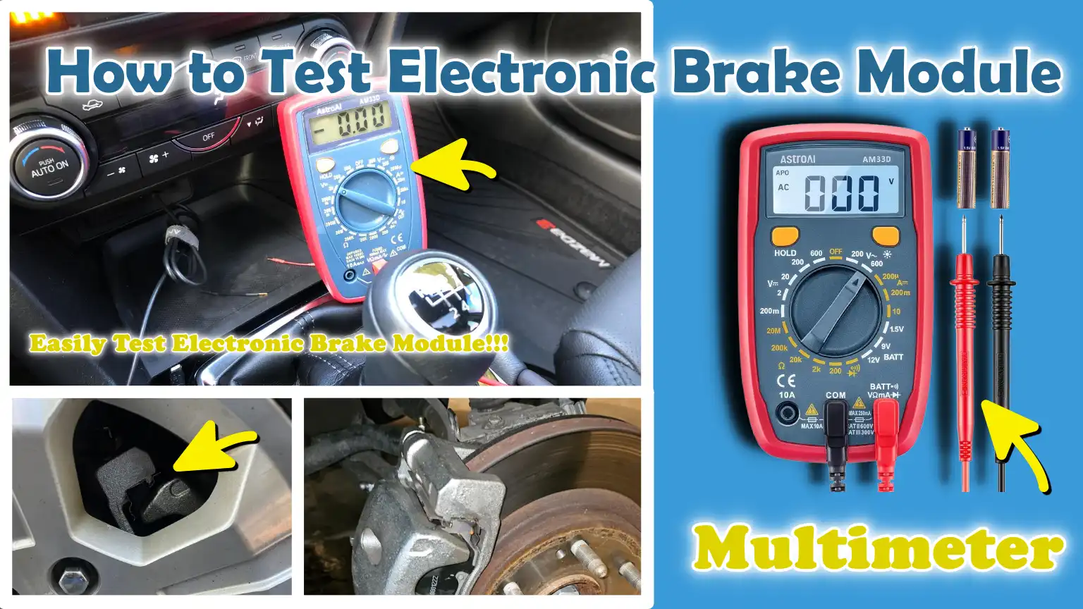
That’s why, you need to learn How to Test Electronic Brake Module (EBCM) so that at least you can check if it is working as intended or not, because just replacing that part directly only got you to expense only.
Know, Common Symptoms of a Faulty Electronic Brake Module
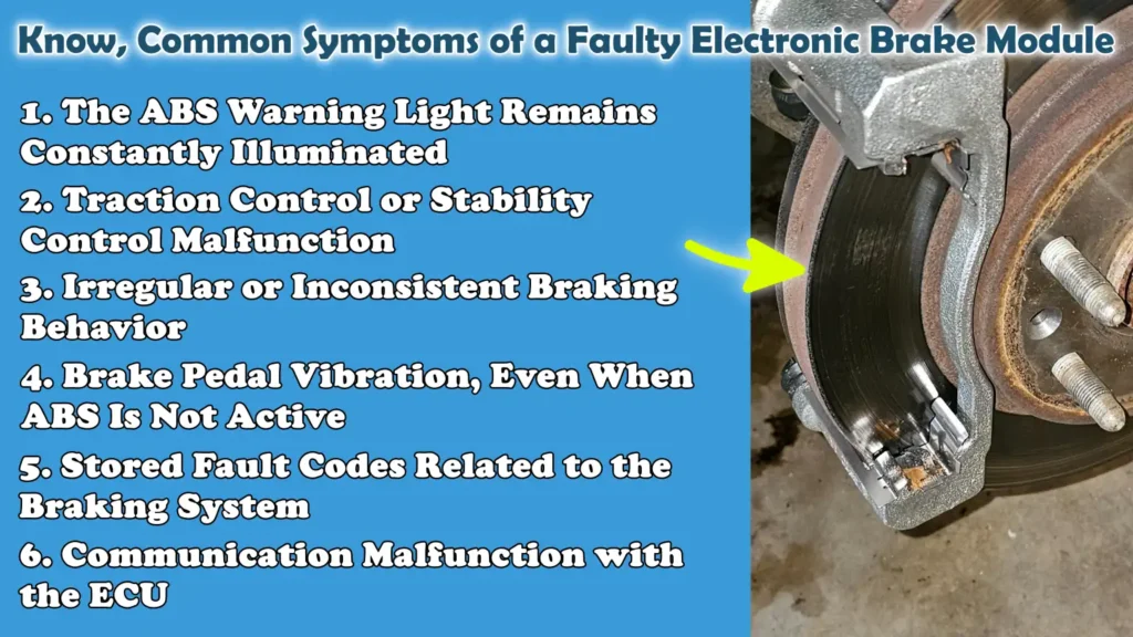
1. The ABS Warning Light Remains Constantly Illuminated
When the ABS warning light remains constantly illuminated, it generally indicates that the electronic brake module has detected a malfunction and has disabled the anti-lock braking system to ensure safe operation.
The ABS system is designed to prevent the wheels from locking up during hard braking; it rapidly adjusts brake pressure multiple times per second.
If the module cannot rely on the data it receives or is unable to properly control the system, it triggers the warning light and shuts the system down.
In this scenario, your vehicle can still brake normally, but it loses the ability to prevent skidding during sudden stops, particularly on wet or slippery roads.
This is often one of the earliest and most common symptoms of a problem within the module or its associated systems.
2. Traction Control or Stability Control Malfunction
The electronic brake module is responsible not only for the ABS but also plays a crucial role in the traction control and stability control systems.
These systems utilize the same sensors and braking controls to help keep the vehicle stable by minimizing wheel spin or correcting the vehicle’s trajectory.
When the module begins to fail, you may face issues such as warning messages, a non-functional traction control system, or a failure of the system to engage when needed.
In actual driving conditions, this may cause the vehicle to feel less stable when taking sharp turns, accelerating suddenly, or driving on loose surfaces.
This occurs because the module is unable to properly process wheel speed data or accurately apply braking force to individual wheels.
3. Irregular or Inconsistent Braking Behavior
A faulty electronic brake module can sometimes result in braking performance that feels inconsistent or unpredictable.
You may press the brake pedal and experience a delayed response, uneven braking force, or a sensation that the vehicle is not slowing down as expected.
This does not necessarily mean that the brakes have failed completely; rather, it indicates that the system responsible for regulating brake pressure is not functioning correctly.
As the module assists in managing the distribution of braking force, any internal malfunction or signal error can lead to erratic behavior, thereby diminishing overall confidence in, and control over, the braking system.
4. Brake Pedal Vibration, Even When ABS Is Not Active
Vibration in the brake pedal is considered normal only when the ABS activates during rapid braking, as the system rapidly applies and releases brake pressure.
However, if you experience vibration during normal braking, when the ABS should not be active, it may signal an issue with the electronic brake module or its associated control signals.
The module may be sending erroneous commands, causing the system to perceive a need for ABS intervention even when no such need exists.
This can confuse the driver and result in a jarring sensation or unevenness during braking, even under light application.
5. Stored Fault Codes Related to the Braking System
Modern vehicles continuously monitor system performance and store fault codes whenever a malfunction occurs.
A defective electronic brake module frequently triggers specific Diagnostic Trouble Codes (DTCs) related to the ABS, pump motor circuits, valve operation, or sensor signals.
These codes are stored in the system’s memory and can be retrieved using a diagnostic scanner.
These codes provide crucial clues regarding the nature of the malfunction, whether it is a power supply issue, a communication error, or a fault within the module itself.
Accurately reading and interpreting these codes is one of the most reliable methods for confirming a specific issue.
6. Communication Malfunction with the ECU
It is essential for the electronic brake module to maintain continuous communication with the main Engine Control Unit (ECU) and other systems via a network known as the CAN bus.
If this communication is interrupted, delayed, or ceases entirely, it can trigger warning lights and lead to system malfunctions.
A failing module may transmit incomplete or erroneous data, or it may stop responding altogether.
This can manifest as diagnostic error messages such as: a loss of communication with the ABS module.
When this occurs, critical safety systems may simultaneously cease to function, thereby compromising the vehicle’s ability to respond effectively in challenging situations.
Tools
| Tools | Why It Is Needed | How to Use It |
|---|---|---|
| OBD-II Scanner with ABS Capability | This tool reads fault codes stored within the brake system. A standard scanner cannot access ABS data; therefore, a scanner with ABS support is required to diagnose issues related to the module. | Connect the scanner to the vehicle’s OBD port, turn on the ignition and select the ABS system from the menu. Read both stored and pending codes. |
| Digital Multimeter | This is used to check electrical values such as voltage, resistance and continuity. The brake module relies on proper power and ground signals; therefore, verifying these connections is crucial. | Set the multimeter to voltage or resistance mode. Place the probes on the module connector pins to check the power supply and ground. Use the continuity mode to test the wiring. |
| Wiring Diagram – Vehicle Specific | Every vehicle has a unique wiring layout. This diagram helps you understand the function of each wire and pinpoints exactly where to perform checks. Without it, diagnosing a problem becomes little more than guesswork. | Consult the diagram to locate the power wires, ground points and communication lines connected to the module. Follow specific circuit paths while conducting your diagnostics. |
| Test Light | This is a simple tool that allows you to quickly determine whether a circuit is receiving power. For basic checks, it is faster than using a multimeter. | Connect the test light’s clip to a ground point and touch the probe to a power wire or fuse. If the light illuminates, it indicates that power is present. |
| Scan Tool with Live Data | This is an advanced tool that displays real-time data from sensors and the brake system. It helps identify issues that may not necessarily manifest as specific fault codes. | Connect the tool, access the live data stream and, while the vehicle is in motion, monitor values such as wheel speed sensor readings and brake signals. |
| Basic Hand Tools | These tools are required to access the brake module, connectors and wiring. Without proper access, the inspection cannot be performed correctly. | Use tools such as screwdrivers, sockets and pliers to remove covers, panels, or mounts in order to safely access the module. |
How to Take Safety Precautions Before Testing
1. Park the Vehicle on a Level Surface and Engage the Parking Brake
Before initiating any testing procedure, always ensure that the vehicle is situated on a level and stable surface and that the parking brake is fully engaged.
This step is critical, as even a slight incline can cause the vehicle to roll, particularly when you are working around the braking system or under the hood.
During testing, the braking system may not be fully functional; therefore, you cannot rely solely on it to keep the vehicle stationary.
Safely securing the vehicle minimizes the risk of sudden, unintended movement, which could result in serious injury or damage.
This allows you to focus entirely on conducting accurate diagnostics without the distraction of potential safety hazards.
2. Disconnect the Battery When Inspecting Wiring
When inspecting wiring, connectors, or the electronic brake module itself, it is absolutely essential to disconnect the battery.
This precaution safeguards against electric shock, short circuits and sudden damage to sensitive electronic components.
Modern brake modules handle low-voltage signals and communication lines; even a minor error such as: accidentally touching the wrong wire, as it can lead to system malfunctions or permanent damage.
Disconnecting the battery also protects you from sparks that may occur when working with metal tools.
Always disconnect the negative terminal first and reconnect it only after all inspections have been completed.
3. Avoid Conducting Tests While the Vehicle is in Motion, Unless You Are Safely Utilizing a ‘Live Scan’ Function
Most testing procedures should be performed only while the vehicle is stationary, as working on a moving vehicle increases safety risks and compromises your control over the vehicle.
However, for certain modern diagnostic procedures such as: reading ‘live data’ from wheel speed sensors, it may be necessary for the vehicle to be in motion.
In such instances, testing must be conducted with the utmost caution; it is advisable to have a second person operate the ‘scan tool’ while the driver focuses their entire attention solely on driving the vehicle.
This minimizes the risk of distraction and ensures safety.
Never attempt to perform complex diagnostic tests alone while driving, as even a minor error could create a hazardous situation on the road.
4. Use Appropriate PPE (Personal Protective Equipment), Such As Gloves and Safety Glasses for Eye Protection
The use of proper Personal Protective Equipment (PPE) is a simple yet critical safety measure that is often overlooked.
Gloves protect your hands from accidental contact with sharp edges, hot surfaces and electrical components.
Eye protection is equally vital, as small particles, dust, or sparks can cause serious injury.
Dirt and brake dust can accumulate within the braking system and should not be allowed to come into contact with your skin or eyes.
Wearing the correct safety gear enables you to work safely and with confidence, particularly when you are working with both electrical and mechanical components simultaneously.
How to Test Electronic Brake Module (EBCM) – Easy to Follow
1. How to Scan for Trouble Codes
Connect an OBD-II Scanner
The first step in testing the electronic brake module is to connect an OBD-II scanner to the vehicle’s diagnostic port.
This port is typically located under the dashboard, near the driver’s seat.
This port allows the scanner to communicate directly with the vehicle’s control systems.
Once connected, turn the ignition key to the “ON” position, but do not start the engine (unless your scanner specifically requires the engine to be running).
This step powers up the electronic systems, enabling the scanner to read data accurately.
It is essential to use a scanner with ABS capability, as basic scanners cannot access information from the brake module.
This connection lays the foundation for accurate diagnosis, as it allows you to see what the system is detecting internally.
Access the ABS or EBCM Module
Once the scanner is connected, navigate through its menus to access the ABS or Electronic Brake Control Module.
Modern vehicles contain multiple control modules and selecting the correct module ensures that you are reading the appropriate data.
The brake module governs functions such as anti-lock braking, traction control and stability control; therefore, accessing it provides direct insight into the status of these systems.
If the scanner fails to connect to this module, it could indicate a significant issue such as: a communication failure or a power-related problem within the module itself.
Successfully accessing the module confirms that it is, at the very least, responding to diagnostic requests.
Record Stored and Pending Codes
Once inside the module interface, the scanner will display any stored and pending trouble codes.
Stored codes indicate faults that the system has already detected and confirmed, while pending codes serve as early warnings for potential issues that have not yet fully manifested.
It is crucial to carefully note or record all codes exactly as they appear, including any accompanying descriptions.
These codes serve as a diagnostic report from the vehicle, pinpointing precisely where the system has detected abnormal behavior.
Recording them also helps you track changes following repairs or further testing, ensuring that no critical information is overlooked.
Understand the Meaning of Common ABS-Related Codes
Understanding the significance of trouble codes is the key to accurate diagnosis.
Codes associated with the ABS often point to a specific component or system such as: a wheel speed sensor, a pump motor circuit, valve operation, or a communication fault between various modules.
For instance, a code related to a wheel speed sensor might indicate that the sensor itself is faulty or that its wiring is damaged; conversely, a communication-related code could signal that the electronic brake module is not properly sending or receiving signals.
It would be incorrect to assume, based solely on a single code, that the fault lies within the module itself, as many issues can stem from wiring problems or sensor malfunctions.
By carefully interpreting the codes and correlating them with the observed symptoms, you can identify the root cause of the problem and avoid unnecessary component replacements.
2. How to Check Power and Ground Supply
Locate the EBCM Connector
The Electronic Brake Control Module (EBCM) is typically mounted near the ABS pump, often located within the engine bay or, in some cases, along the vehicle’s frame.
To diagnose it accurately, you must first locate the main electrical connector that plugs into the module.
This connector carries power, ground and communication signals.
Consulting the vehicle-specific wiring diagram will help you identify the correct connector and pin layout, as vehicle designs vary.
Carefully inspect the connector for any signs of dirt, corrosion, bent pins, or looseness; even a minor issue with the connection can interrupt the electrical flow and make the module appear to be faulty.
Use a Multimeter to Check Voltage Supply
Once the connector has been located, use a digital multimeter to verify that the module is receiving the correct voltage.
Set the multimeter to measure DC voltage and place its probes on the specific power and ground pins indicated in the wiring diagram.
Turn on the ignition to energize the system.
A healthy circuit should display a stable voltage reading close to the battery level, typically around 12 volts in most vehicles.
If there is no voltage, or if the voltage is significantly low or unstable, it indicates that the module is not receiving the power required to operate.
This issue may stem from a blown fuse, damaged wiring, or a faulty relay, rather than a defect within the module itself.
Verify Proper Ground Connection
A robust and stable ground connection is just as critical as the power supply.
The ground path allows electricity to complete its circuit; without it, the module cannot function correctly.
To check the ground connection, set the multimeter to continuity or resistance mode and test between the ground pin and a known, reliable metal surface on the vehicle’s chassis.
The reading should be very low, resistance should be close to zero, indicating a robust connection.
If the resistance is high or unstable, it implies that the ground connection is weak or broken; this can lead to erratic module behavior, communication errors, or even total system failure.
Compare Readings with Manufacturer’s Specifications
After measuring voltage and ground connections, it is crucial to compare your readings against the manufacturer’s specifications provided in the service manual.
These specifications define the correct voltage ranges and acceptable resistance values for the system.
Even minor deviations can signal a problem, particularly in modern electronic systems that rely on precise signals.
Comparing your results ensures that your diagnosis is accurate and not merely based on guesswork.
If the readings fall within the prescribed parameters, it is highly probable that the power and ground circuits are functioning correctly and the issue likely lies within the module itself or another component of the braking system.
3. How to Inspect Wiring and Connectors
Check for Corrosion, Loose Pins and Damaged Wires
Wiring and connectors serve as the pathways that transmit power and signals to the electronic brake module; therefore, even a minor issue in this area can trigger significant problems throughout the entire system.
To begin, visually inspect the connectors and wires connected to the module.
Pay particular attention to corrosion; this often manifests as a green or white powdery film on metal terminals and can impede the flow of electricity.
Check for loose pins that may not be making proper contact, as this can lead to intermittent faults, malfunctions that appear sporadically and then suddenly vanish.
Additionally, look for cracks, cuts, or melted insulation on the wires; such damage can result from heat, vibration, or aging.
These physical defects can disrupt signal transmission between sensors and the module, potentially triggering warning lights or causing system failure.
Check Harness Continuity
Following the visual inspection, the next step is to check the continuity of the wiring harness using a digital multimeter.
A continuity check verifies whether electrical current can flow smoothly and without interruption from one end of a wire to the other.
Set the multimeter to continuity mode and test each wire by placing the probes (test leads) at both ends of the circuit.
A healthy wire will indicate continuous contact, whereas a broken or damaged wire will show no connection or display fluctuating readings.
This step is crucial because certain types of wiring faults are not externally visible, particularly when a wire has broken internally beneath the insulation.
Verifying proper continuity confirms that signals originating from sensors and power sources are successfully reaching the module.
Repair or Replace Faulty Wiring
If any defects or deficiencies are detected in the wiring or connectors, it is crucial to repair them before proceeding with further diagnostics.
Minor issues such as: slight corrosion, as it can sometimes be resolved by using an appropriate electrical contact cleaner; conversely, loose pins may need to be carefully tightened or properly reseated to ensure a secure connection.
However, if a wire is completely severed, heavily corroded, or burnt, the best course of action is to repair it using the correct connectors or to completely replace the damaged section.
Temporary makeshift fixes such as: merely twisting wires together, as it can lead to future complications and are unreliable for critical systems like the brakes.
Proper repairs ensure a stable electrical flow, which is absolutely essential for the module to function correctly and to guarantee full braking safety.
4. How to Verify Communication Using a Scan Tool
Confirm that the module is communicating with the ECU
The Electronic Brake Control Module must constantly exchange information with the vehicle’s main control unit to ensure that systems such as ABS, traction control and stability control can function cohesively and without interruption.
To verify this, connect a scan tool that supports full-system diagnostics and attempt to access the brake module’s data.
If the scan tool is able to access the module and display information, it indicates that communication is functioning at a basic level.
This step is crucial because, even if the power and ground connections are intact, the module is effectively useless if it cannot exchange data with other systems.
Successful communication confirms that the module is active and capable of responding to commands.
Check for ‘No Communication’ Errors
If the scan tool displays a message such as “No Communication with ABS Module” or fails to establish a connection entirely, it is a definitive indication of a deeper underlying issue.
Such errors typically signify that the module is not responding on the network, a situation that may stem from internal malfunctions, wiring issues, or interruptions in the power or ground supply.
In some instances, other vehicle modules may also store communication-related fault codes, which can help corroborate this diagnosis.
It is important to understand that a “No Communication” error does not necessarily imply that the module itself has failed completely; rather, it indicates that something is impeding the proper exchange of data, thereby necessitating further investigation.
Check CAN Bus Signals – If Necessary
Modern vehicles utilize a communication system known as the “Controller Area Network” (CAN), which enables various modules to transmit and receive data over a shared wiring infrastructure.
The electronic brake module relies on this very network to receive sensor data and issue commands.
If a communication issue is suspected, it may be necessary to check the CAN bus signals using a multimeter or an advanced diagnostic tool.
These signals are typically measured as voltage fluctuations that follow a specific pattern.
Any irregular readings such as: a missing signal or unstable voltage, could indicate faulty wiring, a short circuit, or a disruption within the network.
Ensuring the proper functioning of the CAN bus is critical, as no module, even if otherwise in good condition, as it can operate unless it is connected to the rest of the system.
5. How to Analyze Live Data
Monitor Wheel Speed Sensors
Wheel speed sensors are among the most critical inputs for the Electronic Brake Control Module, as they provide the system with precise information regarding how fast each wheel is rotating in real time.
When using a scan tool capable of displaying live data, you can observe the individual rotational speed of each wheel, whether the vehicle is in motion or the wheels are being spun during testing.
Under normal conditions such as: driving in a straight line at a constant speed, the rotational speeds of all wheels should be nearly identical.
If a specific sensor displays a divergent speed, suddenly drops to zero, or provides an erratic reading, it can confuse the module and trigger erroneous braking actions such as: the unwarranted activation of the ABS or the illumination of warning lights.
By monitoring these values, you can quickly pinpoint whether the issue lies with the sensor itself or with how the module is interpreting the data.
Check Brake Pressure Readings – If Available
Some vehicles provide live data regarding brake pressure, indicating the amount of hydraulic force being applied when the brake pedal is depressed.
This information is invaluable because the Electronic Brake Module regulates how pressure is distributed throughout the system during braking, particularly when the ABS is active.
As you depress the brake pedal, the pressure readings should rise progressively and correspond directly to your pedal input.
If the readings are delayed, inconsistent, or do not correlate with the movement of the brake pedal, it may signal a fault within the module, the pressure sensor, or the internal control valves.
Although not all vehicles display this specific data, when it is available, it offers clear insight into how the system is responding in real time.
Compare Sensor Outputs for Consistency
A fundamental aspect of live data analysis involves comparing values received from all relevant sensors to determine whether they are operating consistently and uniformly under identical conditions.
The electronic brake module relies on accurate and balanced data from multiple sensors to make precise decisions.
For instance, if three wheel speed sensors provide consistent readings while a fourth behaves differently, the issue likely lies not within the module itself, but rather with that specific sensor or its associated wiring.
Consistency across these data points validates the reliability of the system’s inputs.
When values do not match or fluctuate unexpectedly, it aids in pinpointing the true root cause of the problem.
This step is critical, as it prevents misdiagnosis and ensures that only the faulty component is repaired or replaced.
6. How to Perform Functional Tests
Activate the ABS Pump using a Scan Tool via Bi-Directional Control
Functional testing allows you to instruct the Electronic Brake Control Module to activate specific components of the system, thereby enabling you to verify whether they are functioning correctly.
By utilizing a Scan Tool that supports Bi-Directional Control, you can send a direct command to activate the ABS Pump without having to drive the vehicle.
This step is crucial because the pump is responsible for generating and releasing hydraulic pressure during ABS operation.
When you initiate this test, the module should respond immediately and activate the pump in accordance with the command.
If the pump fails to activate, activates sluggishly, or operates improperly, it may indicate an issue with the module, the pump motor, or the system’s power supply.
Listen for the Pump Motor’s Operation
When the ABS pump activates, it typically emits a distinct buzzing or humming sound, indicating that the motor is running.
Listening carefully during the test helps confirm whether the pump is genuinely operational.
A healthy pump motor should produce a smooth, consistent sound, free of any interruptions or unusual noises.
If no sound is audible, it may suggest that the motor is not receiving power or has failed internally.
If the sound is faint, rough, or inconsistent, it could indicate internal wear within the motor or an internal electrical fault.
This simple auditory test provides concrete, real-world insight into the system’s operational status, going far beyond merely reading data displayed on a screen.
Check Valve Operation
Inside the ABS unit are small control valves that open and close to regulate the brake fluid pressure at each individual wheel.
These valves are controlled by the Electronic Brake Module and are essential for the proper functioning of the ABS system.
During functional testing, a scan tool can issue commands to actuate these valves, allowing you to verify whether they are operating correctly.
When the valves are actuated, you may hear faint clicking sounds or feel a slight vibration within the system.
The proper operation of these valves ensures that brake pressure can be adjusted rapidly and precisely during emergency braking situations.
If the valves fail to respond or do not function correctly, it may indicate an internal fault within the module or the hydraulic unit, an issue that could adversely affect braking performance and safety.
7. How to Check for Internal Module Failure
No Response Despite Correct Power and Ground
After verifying that the module is receiving the correct voltage and has a solid ground connection, the next step is to check for a response.
If the Electronic Brake Control Module still fails to communicate with a scan tool or does not activate during functional testing, it is a definitive sign of an internal failure.
The module contains complex electronic circuitry and processors that control all braking functions.
If these internal components fail, the module becomes unable to process signals or issue commands, even if power is present.
Identifying this situation is crucial, as it helps you avoid unnecessary repairs to wiring or sensors, when the actual problem lies within the module itself.
Intermittent Faults
One of the most frustrating signs of internal module issues is intermittent faults, problems that appear and disappear without any clear pattern.
You may observe warning lights flickering, the system functioning correctly one moment and failing the next, or fault codes clearing themselves only to reappear later.
These issues are often caused by internal circuit malfunctions, loose connections within the module, or thermal stress that degrades electronic components over time.
Diagnosing intermittent faults is particularly challenging because the system may appear to function normally during testing, yet fail again under actual driving conditions.
Paying close attention to recurring patterns and correlating scan data with observed symptoms can help confirm the presence of such a problem.
Burning Odor or Visible Damage
Although less common, certain physical signs such as: a burning odor, melted plastic, or visible damage to the module housing, as it can indicate a serious internal failure.
These signs typically manifest when the unit has been subjected to internal overheating, a short circuit, or an electrical overload.
Electronic brake modules are designed to handle specific voltage and current levels; any condition exceeding these limits can damage their internal components.
If you observe any of these signs, it is likely that the module is beyond repair and requires replacement.
Prompt identification of visible damage is crucial, as it immediately confirms the issue and eliminates the need for further testing, a process that might otherwise be time-consuming or carry the risk of causing further damage to the system.
Know, Common Electronic Brake Module Fault Codes
1. C0265 – EBCM Relay Circuit
This code typically indicates an issue within the relay circuit responsible for supplying power to the Electronic Brake Control Module (EBCM) or its internal components.
The relay functions as an automatic switch, activating and deactivating the system as needed.
When this circuit malfunctions, the module fails to receive a consistent power supply; consequently, the ABS system may cease to function or behave erratically.
You may observe the ABS warning light remaining continuously illuminated, or the system may fail to respond during diagnostic testing.
The primary causes for this issue may include a faulty relay, defective wiring, loose connections, or, in some instances, an internal defect within the module itself.
Before deeming the module defective, it is crucial to thoroughly inspect both the relay and the power supply circuit.
2. C0241 – Engine Torque Signal Circuit
This code signals a problem with the signal that informs the braking system of the current amount of power being generated by the engine.
The electronic brake module utilizes this information to manage traction control, specifically by reducing engine power or applying the brakes when wheel slippage is detected.
If this signal is missing or inaccurate, the system is unable to properly synchronize with the Engine Control Unit (ECU).
Consequently, the traction control system may become inoperative or function incorrectly.
This issue can stem from communication glitches, wiring faults, or errors in the data being exchanged between the modules.
When this code appears, it is often necessary to inspect both the brake module itself and its communication link with the engine control system.
3. U0121 – Lost Communication with ABS Module
This is a communication-related diagnostic code indicating that other control units within the vehicle are unable to establish communication with the ABS or electronic brake module.
Modern vehicles rely on a networked system that facilitates data sharing between various modules; if the brake module ceases to respond, this specific code is triggered.
The primary causes of this issue may include interruptions in the power or ground supply reaching the module, faulty communication wiring, or a significant internal malfunction within the module itself.
When this code appears, systems such as ABS, traction control and stability control may cease to function, as they are unable to receive the necessary data.
This code often serves as a definitive indication that further testing of the module and network signals is required.
4. C0110 – Pump Motor Circuit
This code points to a fault within the ABS pump motor circuit, the circuit responsible for generating and regulating hydraulic pressure during anti-lock braking operations.
When a fault occurs in this circuit, the pump fails to activate when needed, thereby preventing the ABS system from functioning correctly.
You may observe the ABS warning light illuminating, or you may perceive that the system is failing to engage during hard braking maneuvers.
The underlying cause of this issue could be a defective pump motor, wiring anomalies, a failed relay, or a technical malfunction within the electronic brake module, the unit that controls the motor.
Verifying the operational status of the pump and inspecting the associated electrical circuitry helps in accurately pinpointing the root cause of the problem.
When to Repair and When to Replace the EBCM
1. Minor Wiring or Connector Issues Should Be Repaired
In many cases, issues that appear to indicate a faulty Electronic Brake Control Module (EBCM) are actually caused by minor external problems such as: damaged wiring, loose connectors, or corrosion on terminals.
These issues disrupt the flow of power and signals, making the module appear to be malfunctioning, even though it is technically functioning correctly.
Repairing these issues is generally straightforward and cost-effective.
Cleaning corroded connectors, tightening loose pins, or repairing broken wires can restore proper system communication and performance.
It is always essential to inspect and address these basic issues first; replacing the module without resolving them will not fix the root cause of the problem and the same fault may recur.
2. When Internal Circuits Are Faulty, the Module Must Be Replaced or Rebuilt
When diagnostics confirm that the power, ground, wiring and communication lines are all functioning correctly, yet the module remains unresponsive or reports an internal fault, the root cause of the problem likely lies within the module itself.
The Electronic Brake Control Module contains complex electronic circuits and processors that, in most cases, cannot be easily repaired.
Internal faults can result from exposure to heat, vibration, electrical overloads, or aging components.
In such situations, it is generally necessary to either completely replace the module or have it professionally rebuilt by a specialist.
A “rebuilt” module is repaired by experts who restore its functionality by replacing faulty internal components, while a “new” module offers a complete replacement option.
The decision to choose between these options depends on factors such as availability, cost and reliability.
3. Cost Comparison – Repair vs Module Replacement
Understanding the cost differential helps in making a practical decision.
Repairing wiring or connectors is generally less expensive and less time-consuming; therefore, when the issue is external, this constitutes the best option.
Replacing a module is a more costly undertaking, as the component itself can be expensive and in many vehicles, it also requires programming to integrate it with the vehicle’s systems.
“Remanufactured” modules are often less expensive than new ones and strike a good balance between cost and performance.
However, it is also essential to take into account the labor costs associated with diagnosis and installation.
Choosing the right option hinges on an accurate diagnosis, as replacing a module unnecessarily can result in significant expense while failing to resolve the actual problem.
Read More:
- How to Fix Parking Brake Dragging
- How to Adjust Parking Brake Cable
- How to Check Parking Brake Cable Tension
- How to Fix Brakes Dragging While Driving
- How to Diagnose Brake Dragging Issue
- How to Fix Internal Master Cylinder Leak
- How to Test Brake Master Cylinder Pressure
- How to Replace Brake Booster
- How to Fix Brake Booster Vacuum Leak
- How to Test Brake Booster Functionality
- How to Lubricate Brake Caliper Pins Properly
- How to Rebuild Brake Caliper at Home
- How to Check Brake Caliper Piston Movement
- How to Resurface Brake Rotors at Home
- How to Fix Brake Rotor Runout
How to Test and Replacement Costs
1. Diagnostic Cost Range
The cost of diagnosing a fault in an Electronic Brake Control Module can vary depending on the tools used and the level of testing required.
Basic diagnostic checks, typically performed using a scan tool to read fault codes, are generally quick and inexpensive; conversely, more in-depth testing, which involves examining wiring, power supplies and live data, as it can take longer and increase the overall cost.
In many cases, an accurate diagnosis is the most critical step, as it prevents the unnecessary replacement of parts that are not actually defective.
A thorough diagnostic process ensures that the true root cause of the fault is identified, whether it stems from a faulty sensor, a wiring issue, or the module itself.
Investing the appropriate amount in a correct diagnosis can actually save money in the long run by avoiding unnecessary repairs.
2. Module Replacement Costs
The cost of replacing an Electronic Brake Control Module depends on the vehicle’s make and model, as well as whether you choose a new unit or a remanufactured (rebuilt) unit.
New modules are generally more expensive, as they come directly from the manufacturer and offer complete reliability.
Remanufactured modules are often a more economical option; they are refurbished by specialists who replace any worn or defective internal components.
Prices can vary significantly, as some modules are standalone units with a relatively simple design, while others are integrated with hydraulic units and feature a more complex design.
Choosing a reliable replacement part is crucial, as this module controls essential safety systems such as the ABS (Anti-lock Braking System) and stability control.
3. Labor Charges
Labor charges are determined by the accessibility of the module within the vehicle and the complexity of the replacement procedure.
In some vehicles, the module is easily accessible and can be replaced quickly, resulting in lower labor costs.
In other cases, the module may be located in a cramped or hard-to-reach area, potentially requiring the removal of surrounding components; this can significantly increase the time required to complete the replacement task.
The involvement of a skilled technician is crucial, as improper installation can lead to further malfunctions or damage to the system.
The total labor charge also includes the time spent on testing, both before and after the replacement, to ensure that the system is functioning correctly.
4. Reprogramming Costs: An Essential Step
After replacing an Electronic Brake Control Module, reprogramming is often required to ensure that the new module integrates properly with the vehicle’s systems.
Modern vehicles utilize software coding to interconnect various components; without this step, the module may fail to function correctly, or warning lights may illuminate.
Reprogramming involves loading the appropriate software and calibrating the module to interface with other systems, such as the Engine Control Unit and various sensors.
This procedure requires specialized equipment and is typically performed by a professional.
Although it increases the overall cost, this step is absolutely essential to restore full operational functionality and to ensure that the braking system operates safely and correctly.
How to Prevent Electronic Brake Module Failure
There’s research already that clearly shows that the testing the electronic brake module is really critical, as if the module fails, then the ABS system cannot function in proper way, which directly reduces the driver’s ability to maintain the control during the emergency braking situations.[¹]
1. Regular Maintenance of the Brake System
Regular maintenance of the braking system helps reduce the strain placed on the electronic brake control module and ensures that all associated components continue to function correctly.
This includes checking the level and condition of the brake fluid, inspecting the brake pads and rotors and ensuring that there are no leaks in the hydraulic system.
Clean, high-quality brake fluid is particularly important, as contaminated fluid can compromise pressure control and damage internal components over time.
When the mechanical components of the braking system function correctly, the module does not have to compensate for any malfunctions, thereby extending its lifespan and enhancing its reliability.
2. Keep Connectors Clean and Dry
The electronic brake module relies on stable electrical connections to function properly; therefore, it is essential to keep the connectors clean and dry.
Moisture, dirt and corrosion can accumulate on the connectors and disrupt electrical signals, leading to communication errors or system malfunctions.
Regular inspection of the connectors and associated wiring helps prevent these issues.
If any dirt or corrosion is visible, it should be cleaned using an appropriate electrical contact cleaner.
Protecting the connectors from exposure to water and ensuring that they are securely connected helps maintain a robust and consistent electrical flow.
3. Address Sensor Issues Promptly
Sensors such as: wheel speed sensors, play a critical role in the operation of the electronic brake module.
These sensors provide real-time data, which the module uses to control the braking, traction and stability systems.
If a sensor begins to malfunction or transmits inaccurate data, the module may receive incorrect information and react inappropriately.
Promptly addressing sensor issues prevents the module from operating under abnormal conditions, thereby averting the risk of excessive pressure or internal failure.
Timely repairs also prevent warning lights from illuminating and ensure that the system continues to function exactly as intended.
4. Avoid Driving When the ABS Warning Light Is Illuminated
Driving while the ABS warning light is illuminated indicates that the system has detected a malfunction and may have disabled critical safety features.
Even if standard braking remains functional, the vehicle loses its advanced capabilities such as: anti-lock braking and stability control, which are indispensable during emergency situations.
Continuing to drive under these circumstances can cause minor issues to escalate into more serious problems over time.
Resolving the issue as soon as the warning light appears helps prevent further damage and ensures that the electronic brake module and its associated systems remain reliable and safe.
Conclusion – How to Test Electronic Brake Module
In today’s driving you need to really understand about the electronics as it is the important part of vehicle that almost controls everything from brakes to everything you name it.
This module serves as a central hub for critical safety features such as: anti-lock braking, traction control and stability control, and even a minor malfunction within it can significantly impact your vehicle’s responsiveness in real-world driving conditions.
Throughout this comprehensive guide, you have observed that issues often stem from minor anomalies such as: wiring faults, power supply deficiencies, or sensor malfunctions, rather than solely from a defect within the module itself.
Therefore, adopting a step-by-step diagnostic process is paramount, as it enables you to pinpoint the root cause of the problem instead of relying on guesswork or unnecessarily replacing expensive components.
Accurate diagnosis is the key to ensuring both safety and cost savings.
By checking trouble codes, verifying power and ground connections, inspecting wiring, analyzing live data and conducting functional tests, you gain a clear and precise picture of the system’s operational status.
This systematic approach not only boosts your confidence during repairs but also ensures that the braking system functions exactly as it was designed to, particularly during those critical moments when its reliability is needed most.
Now, that’s all from this guide from How to Test Electronic Brake Module, also you can comment down below for more information.
Frequently Asked Questions
FAQ 1: What exactly does the Electronic Brake Control Module do?
Answer: The Electronic Brake Control Module acts as the “brain” of your vehicle’s braking system. It gathers data from various sensors such as: wheel speed sensors, and then controls how braking force is applied. It manages critical safety systems like ABS (Anti-lock Braking System), traction control and stability control. When you press the brake pedal, this module helps determine exactly how much pressure to apply to each individual wheel, particularly during sudden stops or on slippery surfaces. If this module malfunctions, many of your vehicle’s advanced safety features will cease to function, even if the basic braking system remains operational.
FAQ 2: Can I drive with a faulty Electronic Brake Control Module?
Answer: Yes, in many cases, the vehicle can still be driven because the basic braking system will continue to function. However, driving in this condition for an extended period is not considered safe. When the module fails, systems such as ABS and stability control typically become disabled. This means that during emergency braking, or while driving on wet or uneven roads, the vehicle may be prone to skidding or losing traction. Driving in this condition increases the risk of an accident; therefore, it is best to have the issue diagnosed and repaired as soon as possible.
FAQ 3: What are the most common symptoms of a faulty Electronic Brake Control Module?
Answer: The most common symptoms include a persistently illuminated ABS warning light, a non-functional traction control system and erratic vehicle behavior during braking. Some drivers may notice that the brake pedal feels different than usual, or that the system activates the ABS when it is not actually needed. In some instances, communication errors may also occur, preventing diagnostic tools from connecting to the module. These warning signs often appear early on and should not be ignored, as failing to address them can lead to even more serious problems.
FAQ 4: How long does it take to inspect an Electronic Brake Control Module?
Answer: The time required depends on the intricacies of the inspection. A basic scan for trouble codes may take just a few minutes. However, a comprehensive diagnostic procedure, which involves checking wiring, testing power and ground connections, analyzing live data and performing functional tests, as it can take anywhere from one to two hours, or even longer. This additional time is essential for accurately identifying the problem, thereby avoiding unnecessary repairs.
FAQ 5: Can the Electronic Brake Module be repaired instead of being replaced?
Answer: In some cases, yes. If the issue lies with the wiring, connectors, or external components, it can often be repaired quite easily. In the event of an internal fault, some modules can be repaired by specialists who work on internal circuitry. However, not all modules are repairable and sometimes replacement remains the only reliable option. This decision depends on the nature of the fault, the associated costs and the availability of repair services.
FAQ 6: Do I need to reprogram the module after replacing it?
Answer: Yes; in most modern vehicles, it is necessary to reprogram the Electronic Brake Module after replacing it. The new module must be calibrated to match the vehicle’s specific systems so that it can communicate correctly with other control units. Without proper programming, the system may fail to function correctly, or warning lights may remain illuminated. This task typically requires specialized tools and software and is therefore often performed by professionals.
FAQ 7: What tools are required to inspect an Electronic Brake Module?
Answer: The most essential tool is a diagnostic scanner capable of accessing the ABS system. A digital multimeter is also required to check voltage levels and verify the integrity of the wiring. For more advanced diagnostics, a scan tool capable of displaying live data and providing bi-directional control is helpful; this aids in monitoring sensor readings and actuating components such as the ABS pump. Basic hand tools are needed to access the modules and connectors. Using the appropriate tools makes the diagnostic process more accurate and efficient.
References:
[1] NHTSA Light Vehicle Antilock Brake System Research Program Task 7.2:, Examination of ABS-Related Driver Behavioral Adaptation – On-Road MicroDAS Study
https://www.nhtsa.gov/sites/nhtsa.gov/files/nhtsaabs7-2finalreport.pdf
Hello Folks, Dean Shali here to help you out to solve the problems with your lovely vehicle, as i have lots of experience and knowledge about automotive industry as i woks directly with the customers and repair vehicles and i love to help the people to keep their cars safe and running smoothly.